
[TOC]
Introduction
Over the course of the last few entries, I documented my learning of Cumulus Linux, and how to do simple VXLAN with an EVPN control plane using their OS. All of this was done in a virtual environment on my server or my Mac laptop. One of the challenges of doing this in an actual network is the port density of the white box switches that run Cumulus. For the most part, they’re 1RU, top of rack switches. These work well for leaf switches, but what happens if you want a more-dense spine switch? One that could have multiple different port speeds and types, and the flexibility to easily change the hardware configuration with line cards? Unfortunately, Cumulus doesn’t run on any of those kinds of switches.
This document will outline my attempt to get Cumulus leaf nodes working with Arista spines as far as EVPN and VXLAN.
Overall System Reliability Primer
I’ve mentioned in previous entries that I’d rather not engineer VXLAN-based leaf/spine networks with a service leaf layer. Recall that the service leaf layer is usually the entry/egress point of the entire VXLAN fabric. It’s an active participant in the exchange of VXLAN information (MAC addresses) and it helps send incoming traffic destined for a resource on another leaf directly to that leaf via the spine layer.
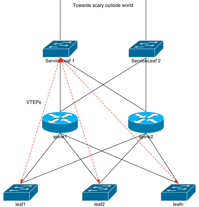
Remember that in a leaf/spine architecture with passive spines, the spine layer only knows about BGP routes. It doesn’t have any view into the L2 that’s flowing through it via the VXLAN tunnels. So if we remove the service leaf layer from the picture and terminate the “scary outside world” directly into the spines, there’s a good chance that a packet destined for a server hanging off, say, leaf5 might hit leaf1 first. Each leaf is announcing that same VLAN’s prefix in BGP up to the spine, and the spine only knows to ECMP packets to the leaf layer. It doesn’t know that the server is actually on leaf5. But, the packet will get to the server. It’ll just hair-pin:
spine –> leaf1 –> spine –> leaf5 –> server
In fact, the more spines you have participating in this, the greater the chance the incoming packet will have to hairpin. For n leaf nodes, the chance of the packet hair-pinning is (100 – (100/n))%.
That Annoying Reliability Formula
If you’d like to read up on this from another source, check this out.
We have to agree on defining the word “reliability” as a decimal number between 0 and 1. A device with 0 reliability means it fails 100% of the time. We don’t want those devices in our system. A device with a 1 reliability means that it never fails. Ever. And those devices don’t exist in technology (or anywhere else in the world). Everything breaks. Even simple cables. That means reliability is a fraction. This comes into play.
The image above along with most other network designs you see have a bunch of devices in parallel connected to a bunch more devices in parallel. With those parallel-connected devices, it might seem like systems would use the parallel-connection reliability formula. But they don’t. They use the series formula, which is simply represented like this:
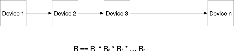
That means that the more devices you have in the path, the less reliable it becomes. Simply: the more fractions you multiply together, the smaller the resulting fraction ends up. If you replace “Device” with “Layer”, you get the idea. In our diagram above, an incoming packet has to flow through the service leaf layer, then the spine layer, then the leaf layer, and then to the server. In other words, the reliability of that can be represented as:
Rsystem == Rservice * Rspine * Rleaf * Rserver
So wouldn’t it stand to reason that if we can remove some of those hops (within reason!), the more reliable a system we can make? Mathematically: the answer is yes. So let’s knock that service leaf layer right out of the picture completely.
A Note About Overall Reliability
If you want to get reeeeeallllly granular about the reliability calculations, you’d have to include the cables’ reliability in the calculations. That includes the optics, which might have their own reliability numbers. It can get a bit onerous to perform these calculations. At certain points various devices’ reliability is so close to 1 it makes little difference if you include their numbers. Such is the case with cables.
Arista Chassis Spines
I understand that folks may disagree with some of the opinions I present here. That’s fine. Fortunately there are a few good ways to build a reliable and scalable network and no one answer is 100% right. My experience is based on nearly a quarter of a century of doing this at large scale. Let that sink in for a moment. I’ve been doing this for nearly 25 years. And in that time, I’ve learned a bunch, I’ve built a bunch, I’ve broken a bunch, I’ve repaired and troubleshot a bunch. As I’ve stated in previous documents, the leaf/spine architecture isn’t new. We were building 2-router-lots-of-switches networks at AOL back in the mid-90s.
With that out of the way, my opinion is that for large scale data centers, it makes more sense to have a chassis as the spine when you can. A four to eight slot chassis gives you the flexibility to have multiple different kinds of downlink port speeds and configurations; easier physical maintenance (a’la quick line card swaps), and usually more resources available in that box. I’m not 100% opposed to using 1RU devices as spines, but what happens with the spine layer runs out of ports? The answer is the same when the chassis runs out of line card slots: you need more spines. Which means you need an aggregate layer above the spines that can move data quickly both north/south and east/east.
Please don’t get me wrong: this can and will happen with both types of spine builds. You can easily run out of ports on a chassis, just like you can with a 1RU box. But it will happen far sooner with the 1RU box. I assume that’s readily apparent to the reader.
L2 On The Spine
Hopefully I’ve spent enough time and space explaining why I want VLAN knowledge at the spine layer. So, from this point forward, I’m going to assume the ingress/egress point for the network is the spine layer, and not a service leaf layer. And we’re going to assume efficient packet handling from the spine layer directly to the appropriate leaf node, which means VXLAN on the spine.
Arista
The challenge is: who’s chassis-based switch to use? And will it inter-op properly with Cumulus’ most-excellent EVPN and VXLAN implementation? Well, in my recent history, Arista does provide a fairly dense and flexible chassis solution. And they’re usually priced much less expensively than Cisco’s solutions are, depending on which ones you look at. The question is back to: can we make it work?
The answer is, ultimately: yes. But it took me a little while to get there.
Arista vEOS on Bhyve
Thankfully, Arista provides a virtual version of their EOS, called vEOS. They provide it in various image formats including VMWare’s VMDK. And if you read some of my older documents, you’ll remember that Arista used to require that you use their boot image along with the vEOS image. Basically, the VM had to boot off a virtual CDROM image (ISO), and then continue booting with the VM image. They’ve done away with that and now have an all-in-one image.
VMDK’s don’t work with bhyve, but the qemu-img command can fix that:
qemu-img convert -f vmdk -O raw vEOS-lab-4.20.10M-combined.vmdk arista.raw
Once that completed, I had an image ready to use with the Bhyve hypervisor.
My intent for this experiment was to just add two more spine nodes to the network to see if they worked. So when all was in place, the network would look like this:
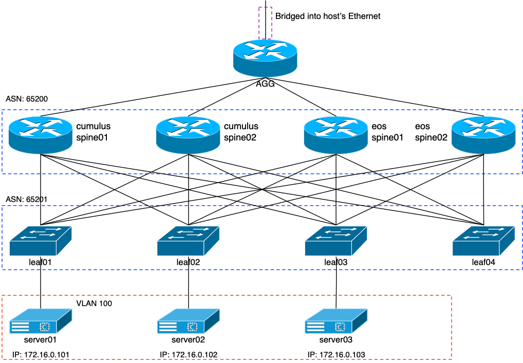
The two spine devices on the right side of the image would be Aristas. This means that I had to add two new interfaces to the agg router, along with the four leaf nodes. A series of calls to the vm switch create command and the following were created:
NAME         TYPE      IFACE           ADDRESS  PRIVATE  MTU   VLAN  PORTS
espn01-lf01  standard  vm-espn01-lf01  -        no       9000  -     -
espn01-lf02  standard  vm-espn01-lf02  -        no       9000  -     -
espn01-lf03  standard  vm-espn01-lf03  -        no       9000  -     -
espn01-lf04  standard  vm-espn01-lf04  -        no       9000  -     -
espn02-lf01  standard  vm-espn02-lf01  -        no       9000  -     -
espn02-lf02  standard  vm-espn02-lf02  -        no       9000  -     -
espn02-lf03  standard  vm-espn02-lf03  -        no       9000  -     -
espn02-lf04  standard  vm-espn02-lf04  -        no       9000  -     -
agg-espn01   standard  vm-agg-espn01   -        no       -     -     -
agg-espn02   standard  vm-agg-espn02   -        no       -     -     -
Config File for Bhyve VM
I’ll admit this took me a long time. A lot of trial and error. Fortunately I knew it could work and am stubborn enough to keep at it until it did. The basic challenge was trying to make sure the vEOS grub would be reference properly by Bhyve. I’m going to ignore all of the interface and switch config parts of the VM for now, and just focus on the booting part. This is what was required in the config file to make the VM boot properly:
disk0_type="ahci-hd"
disk0_name="eos-spine01.img"
guest="linux"
loader="grub"
grub_run0="linux (hd0,msdos1)/linux"
grub_run1="initrd (hd0,msdos1)/initrd
grub_run2="boot"
With that, a simple
vm start eos-spine01
kicked the VM off and it did eventually boot.
Trust me, I came up with a lot of interesting combinations of my favorite four-letter words trying to figure this one out. That was hard part #1.
Base Configuration
To get the Arista images running so that I could ssh into their management interface, I added the following:
username jvp privilege 15 secret sha512 <key>
!
hostname eos-spine01
!
vrf definition mgmt
!
interface Management1
   vrf forwarding mgmt
   ip address dhcp
!
ip route vrf mgmt 0.0.0.0/0 192.168.10.254
This allowed me to ssh in as jvp, versus the Arista “admin” user. The rest of the configuration bits will be shown through this document.
Cumulus and Arista: A Match Made In …
I’m no stranger to configuring Arista devices for the most part. I’ve been using them on and off for six or so years. If you know Cisco’s IOS, you know Arista’s EOS. Fortunately, Arista has made a bunch of things really simple to configure, but not quite as simple as Cumulus has. And: what I haven’t done with Arista yet is configure up their EVPN solution. I took a break from driving Arista switches back in 2017, and that was just prior to them (finally!) launching EVPN.
Interface Configuration
Cumulus: BGP unnumbered. Everything just works.
Arista: What’s BGP unnumbered? …
To anyone reading this who happens to work for one of the big network vendors: USE BGP UNNUMBERED! For crying out loud, it makes things so vastly more simple and easy to get going. Really. We have to get away from this whole IPv4 addressing thing and just use link local! Unfortunately, since Arista doesn’t support unnumbered, I had to add IP addresses to the Arista spine interfaces, along with the interfaces on my leaf nodes.
Cumulus Changes in Ansible
My inventory file had to be changed a bit, once again, because I needed to add static IPs to the leaf nodes’ swp4 and swp5 interfaces. The leaf section of my hosts file:
[leaf]
leaf01 lo0=10.100.0.3 hostname=leaf01 vl100=172.16.0.4 swp4=10.0.6.1 swp5=10.0.7.1
leaf02 lo0=10.100.0.4 hostname=leaf02 vl100=172.16.0.5 swp4=10.0.6.3 swp5=10.0.7.3
leaf03 lo0=10.100.0.5 hostname=leaf03 vl100=172.16.0.6 swp4=10.0.6.5 swp5=10.0.7.5
leaf04 lo0=10.100.0.6 hostname=leaf04 vl100=172.16.0.7 swp4=10.0.6.7 swp5=10.0.7.7
My interfaces playbook had to change a bit, too. I’ll just show the additions below:
---
  - name: Configure swp interfaces
    nclu:
      commands:
      - add interface swp1-5
      - add interface swp4-5 mtu 9000
      - add interface swp4 ip address {{ swp4 }}/31
      - add interface swp5 ip address {{ swp5 }}/31
      - add dhcp relay interface swp4
      - add dhcp relay interface swp5
      atomic: true
Arista
These interface configurations aren’t terribly difficult, but listed here for the first EOS spine:
interface Ethernet1
   description agg:swp4
   no switchport
   ip address 10.0.3.5/31
!
interface Ethernet2
   description leaf01:swp4
   mtu 9000
   no switchport
   ip address 10.0.6.0/31
!
interface Ethernet3
   description leaf02:swp4
   mtu 9000
   no switchport
   ip address 10.0.6.2/31
!
interface Ethernet4
   description leaf03:swp4
   mtu 9000
   no switchport
   ip address 10.0.6.4/31
!
interface Ethernet5
   description leaf04:swp4
   mtu 9000
   no switchport
   ip address 10.0.6.6/31
!
interface Loopback0
   ip address 10.100.0.7/32
BGP and EVPN
Cumulus: BGP and EVPN run fine over the same peer
Arista: Huh? You’re going to EVPN-peer via the loopbacks, right?
Oi. Cumulus, again, makes this ridiculously easy. Do you want that BGP peer on your unnumbered interface to support IP? Cool. Done. Want it to support EVPN as well? No sweat. Done. It doesn’t work that way with Arista; at least I couldn’t get it to. Perhaps I did something wrong.
One of Arista’s solution, if you read through their guides, is that you get an IP EBGP peer going via the interface IPs, and then make sure that you inject the /32 of the loopback into BGP. When you configure EVPN, you do so via the loopback interfaces using EBGP multihop.
Cumulus Changes in Ansible
Again, I made use of my BGP playbook to alter the configurations on the leaf nodes. Here are the additions and changes to the file:
---
  - name: BGP with EVPN
    nclu:
      commands:
      - add bgp neighbor eos-spine peer-group
      - add bgp neighbor eos-spine remote-as external
      - add bgp neighbor eos-spine update-source lo
      - add bgp neighbor eos-spine ebgp-multihop 3
      - add bgp neighbor swp4 interface peer-group spine
      - add bgp neighbor swp5 interface peer-group spine
      - add bgp neighbor 10.100.0.7 peer-group eos-spine
      - add bgp neighbor 10.100.0.8 peer-group eos-spine
      - del bgp ipv4 unicast neighbor eos-spine activate
      - add bgp l2vpn evpn  neighbor eos-spine activate
      atomic: true
The key points being:
- Add interfaces swp4 and swp5 to the existing “spine” peer-group
- Create an “eos-spine” peer group for EVPN peering via the loopback interface
- Add the loops of the EOS spines as peers in the aforementioned group
Arista
The Arista BGP config is, once again, pretty simple. It’s annoying that they don’t seem to allow the same peer to handle both IP and EVPN. But, as I stated previously, perhaps they do and I was just making a mistake. In any event:
router bgp 65200
   maximum-paths 16 ecmp 16
   bgp listen range 10.0.6.0/24 peer-group leaf remote-as 65201
   bgp listen range 10.100.0.0/24 peer-group leaf-evpn remote-as 65201
   neighbor leaf peer-group
   neighbor leaf remote-as 65201
   neighbor leaf fall-over bfd
   neighbor leaf send-community extended
   neighbor leaf maximum-routes 12000
   neighbor leaf-evpn peer-group
   neighbor leaf-evpn remote-as 65201
   neighbor leaf-evpn update-source Loopback0
   neighbor leaf-evpn ebgp-multihop 3
   neighbor leaf-evpn send-community extended
   neighbor leaf-evpn maximum-routes 12000
   neighbor 10.0.3.4 remote-as 65210
   neighbor 10.0.3.4 fall-over bfd
   neighbor 10.0.3.4 allowas-in 3
   neighbor 10.0.3.4 maximum-routes 12000
   redistribute connected
   !
   address-family evpn
      bgp next-hop-unchanged
      no neighbor leaf activate
      neighbor leaf-evpn activate
   !
   address-family ipv4
      no neighbor leaf-evpn activate
Per the above configuration snippet:
- Create a “leaf” peer-group for IPv4 peering via the physical interfaces
- Create a “leaf-evpn” peer-group for EVPN peering via the loopback interface
- Listen for anything on the physical interfaces, and add it automatically to the “leaf” group
- Listen for anything in the loopback range (10.100.0.0/24) and add it automatically to the “leaf-evpn” group
Do We Have BGP and EVPN?
After firing off the ansible-playbook command and letting it change the configs on the 4 leaf nodes, the results on the EOS spines looked promising:
eos-spine01#show ip bgp sum
BGP summary information for VRF default
Router identifier 10.100.0.7, local AS number 65200
Neighbor Status Codes: m - Under maintenance
  Neighbor         V  AS           MsgRcvd   MsgSent  InQ OutQ  Up/Down State  PfxRcd PfxAcc
  10.0.3.4         4  65210           1830        72    0    0 01:29:55 Estab  18     18
  10.0.6.1         4  65201           1382        81    0    0 01:08:27 Estab  4      4
  10.0.6.3         4  65201           1730       233    0    0 01:25:34 Estab  4      4
  10.0.6.5         4  65201           1786        44    0    0 01:28:24 Estab  4      4
  10.0.6.7         4  65201           1648       134    0    0 01:21:38 Estab  4      4
eos-spine01#show bgp evpn sum
BGP summary information for VRF default
Router identifier 10.100.0.7, local AS number 65200
Neighbor Status Codes: m - Under maintenance
  Neighbor         V  AS           MsgRcvd   MsgSent  InQ OutQ  Up/Down State  PfxRcd PfxAcc
  10.100.0.3       4  65201           1823      2129    0    0 01:30:05 Estab  4      4
  10.100.0.4       4  65201           1825      2124    0    0 01:30:05 Estab  4      4
  10.100.0.5       4  65201           1825      2121    0    0 01:30:05 Estab  4      4
  10.100.0.6       4  65201           1646      1917    0    0 01:21:34 Estab  1      1
Is the EOS spine seeing the MAC address announcements from the leaf nodes? The above results would indicate it is, but let’s make sure:
eos-spine01#show bgp evpn vni 10100
BGP routing table information for VRF default
Router identifier 10.100.0.7, local AS number 65200
Route status codes: s - suppressed, * - valid, > - active, # - not installed, E - ECMP head, e - ECMP
                    S - Stale, c - Contributing to ECMP, b - backup
                    % - Pending BGP convergence
Origin codes: i - IGP, e - EGP, ? - incomplete
AS Path Attributes: Or-ID - Originator ID, C-LST - Cluster List, LL Nexthop - Link Local Nexthop

         Network             Next Hop         Metric  LocPref Weight Path
 * >     RD: 10.100.0.3:2 mac-ip 589c.fc00.5e43
                             10.100.0.3       -       100     0      65201 i
 * >     RD: 10.100.0.3:2 mac-ip 589c.fc00.5e43 172.16.0.101
                             10.100.0.3       -       100     0      65201 i
 * >     RD: 10.100.0.3:2 mac-ip 589c.fc00.5e43 fe80::5a9c:fcff:fe00:5e43
                             10.100.0.3       -       100     0      65201 i
 * >     RD: 10.100.0.5:2 mac-ip 589c.fc08.d42e
                             10.100.0.5       -       100     0      65201 i
 * >     RD: 10.100.0.5:2 mac-ip 589c.fc08.d42e 172.16.0.103
                             10.100.0.5       -       100     0      65201 i
 * >     RD: 10.100.0.5:2 mac-ip 589c.fc08.d42e fe80::5a9c:fcff:fe08:d42e
                             10.100.0.5       -       100     0      65201 i
 * >     RD: 10.100.0.4:2 mac-ip 589c.fc0d.3123
                             10.100.0.4       -       100     0      65201 i
 * >     RD: 10.100.0.4:2 mac-ip 589c.fc0d.3123 172.16.0.102
                             10.100.0.4       -       100     0      65201 i
 * >     RD: 10.100.0.4:2 mac-ip 589c.fc0d.3123 fe80::5a9c:fcff:fe0d:3123
                             10.100.0.4       -       100     0      65201 i
 * >     RD: 10.100.0.3:2 imet 10.100.0.3
                             10.100.0.3       -       100     0      65201 i
 * >     RD: 10.100.0.4:2 imet 10.100.0.4
                             10.100.0.4       -       100     0      65201 i
 * >     RD: 10.100.0.5:2 imet 10.100.0.5
                             10.100.0.5       -       100     0      65201 i
 * >     RD: 10.100.0.6:2 imet 10.100.0.6
                             10.100.0.6       -       100     0      65201 i
 * >     RD: 65200:100 imet 10.100.0.7
                             -                -       -       0       i
So far, so good.
L2 and VXLAN
Up to this point, the EOS spines could easily ping any of the three servers in the 172.16.0.0/24 prefix. They were receiving that /24 from the four leaf nodes below them, and were ECMP’ing accordingly. If the wrong leaf for the packet, it would encapsulate it into VXLAN and send it to the appropriate leaf. If I wanted a “good enough” network, this would be fine and I’d be done.
Good enough isn’t.
interface Vlan100
   ip address 172.16.0.8/24
!
interface Vxlan1
   vxlan source-interface Loopback0
   vxlan udp-port 4789
   vxlan vlan 100 vni 10100
This was attempt #1 to get VXLAN on the EOS spine side working. It brought the VLAN100 interface up, but all that did was destroy routing to the 172.16.0.0/24 VLAN. VXLAN was just not working at all. The fixes were a lot easier than I originally thought they’d be, but it took some kind folks at Arista and their support forums to help me through it.
VLAN Interface
The first challenge was that I put a real IP address on the VLAN100 interface. One of the Arista engineers strongly encouraged me to get rid of that, and, instead, use the same virtual IP that I was using on the leaf side: 172.16.0.1. This would require using the same virtual MAC address as well. So, in other words:
interface Vlan100
   ip address virtual 172.16.0.1/24
!
ip virtual-router mac-address 44:39:39:ff:40:94
That still didn’t fix it. It took a lot of back-and-forth on their forums before someone named Alex at Arista was able to figure it out. I was too heavily relying on Cumulus’ ease of configuration, and expecting it to just work on the Arista. Unfortunately: it doesn’t work that way.
Route Target
This was ultimate the crux. If we look at some of the EVPN detail of one of the MAC address announcements, for instance, we see:
BGP routing table entry for mac-ip 589c.fc00.5e43 172.16.0.101, Route Distinguisher: 10.100.0.3:2
 Paths: 1 available
  65201
    10.100.0.3 from 10.100.0.3 (10.100.0.3)
      Origin IGP, metric -, localpref 100, weight 0, valid, external, best
      Extended Community: Route-Target-AS:65201:10100 TunnelEncap:tunnelTypeVxlan
      VNI: 10100 ESI: 0000:0000:0000:0000:0000
No matter what I tried, I couldn’t ping 172.16.0.101 from the EOS spine. The route, or MAC address if you will, just wouldn’t get installed properly into the forwarding table (FIB). The second-to-last line in that readout is what tipped Alex off: I needed to properly specify the import route-target to match the Route-Target-AS. Initially, I had this in the BGP section of the spine:
router bgp 65200
   !
   vlan 100
      rd 65200:100
      route-target both 65200:100
      redistribute learned
Alex suggested that I add an import line so that the spine could make use of those announcements. In other words:
router bgp 65200
   !
   vlan 100
      rd 65200:100
      route-target both 65200:100
      route-target import 65201:10100
      redistribute learned
And that was the magic.
eos-spine01#ping 172.16.0.101
PING 172.16.0.101 (172.16.0.101) 72(100) bytes of data.
80 bytes from 172.16.0.101: icmp_seq=1 ttl=63 time=32.7 ms
80 bytes from 172.16.0.101: icmp_seq=2 ttl=63 time=30.5 ms
80 bytes from 172.16.0.101: icmp_seq=3 ttl=63 time=39.1 ms
80 bytes from 172.16.0.101: icmp_seq=4 ttl=63 time=37.4 ms
80 bytes from 172.16.0.101: icmp_seq=5 ttl=63 time=49.9 ms

--- 172.16.0.101 ping statistics ---
5 packets transmitted, 5 received, 0% packet loss, time 68ms
rtt min/avg/max/mdev = 30.561/37.981/49.945/6.743 ms, pipe 4, ipg/ewma 17.020/35.850 ms
eos-spine01#show ip route 172.16.0.101

VRF: default
Codes: C - connected, S - static, K - kernel,
       O - OSPF, IA - OSPF inter area, E1 - OSPF external type 1,
       E2 - OSPF external type 2, N1 - OSPF NSSA external type 1,
       N2 - OSPF NSSA external type2, B I - iBGP, B E - eBGP,
       R - RIP, I L1 - IS-IS level 1, I L2 - IS-IS level 2,
       O3 - OSPFv3, A B - BGP Aggregate, A O - OSPF Summary,
       NG - Nexthop Group Static Route, V - VXLAN Control Service,
       DH - DHCP client installed default route, M - Martian,
       DP - Dynamic Policy Route

 C      172.16.0.0/24 is directly connected, Vlan100

eos-spine01#show arp 172.16.0.101
Address         Age (min)  Hardware Addr   Interface
172.16.0.101            -  589c.fc00.5e43  Vlan100, Vxlan1
eos-spine01#show vxlan add
          Vxlan Mac Address Table
----------------------------------------------------------------------

VLAN  Mac Address     Type     Prt  VTEP             Moves   Last Move
----  -----------     ----     ---  ----             -----   ---------
 100  589c.fc00.5e43  EVPN     Vx1  10.100.0.3       1       0:00:27 ago
 100  589c.fc08.d42e  EVPN     Vx1  10.100.0.5       1       0:23:54 ago
 100  589c.fc0d.3123  EVPN     Vx1  10.100.0.4       1       0:23:54 ago
Total Remote Mac Addresses for this criterion: 3
The spine now has L2 knowledge of the individual servers that are hanging off the leaf nodes, and will direct incoming traffic for them to the appropriate leaf via VXLAN. Just like the Cumulus spines do.
Wrap-Up and Summary
I’ll end this the way I started it: I know that having fat, chassis-based spines isn’t a popular design choice. And, I also know that a lot of folks want to continue building their networks with the service leaf layer. Hopefully I’ve shown why I still think that architecture is sub-optimal, and why having the flexibility of a chassis at the spine layer is more appealing to me than a 1RU switch. Arista’s EVPN configuration isn’t difficult at all, though it is a bit more involved than Cumulus’. Once properly configured, the two OS will co-exist and properly exchange L2 and L3 information as needed.
1 thought on “Cumulus and Arista EVPN Configuration”