I began writing a few posts on my blog about the use of EVPN as a control plane for VXLAN almost five years ago. At the time I was just becoming familiar with that extension to BGP, and how it could control VTEP bring-ups and tear-downs based on L2 VNIs. What I hadn’t completely grasped at the time was the benefit of using those two technologies for L3 VNIs. Certainly, when working in a typical data center, L2 VNIs are probably more useful as you’ll get the usual, “I need VLAN 100 in all of these racks!” requirement from your server owners. But, as it turns out, L3 VNis are just as useful in the data center when you consider separating your workloads out on the same infrastructure.
Before I go any further, I’m going to assume some basic understanding of BGP, VRFs, VXLAN, and EVPN.
Workload Separation
What do I mean by workload separation? Well let’s say that you have a bunch of customers in your data center, either internal or external to your company, and you’ve classified them into different groups. What, why, and how you’ve classified those groups isn’t important for this discussion. Just that you did it. Now, certainly within a group of customers, you want to have the appropriate levels of security between each host and/or each network. But for whatever reason, you don’t ever want servers in one group to be able to see, communicate with, or even know about the servers in another group.
You could, of course, tighten down the network security between the groups making it harder for inter-group communication to happen. But there’s a better way: make it so that the network can’t let them communicate.
Infrastructure
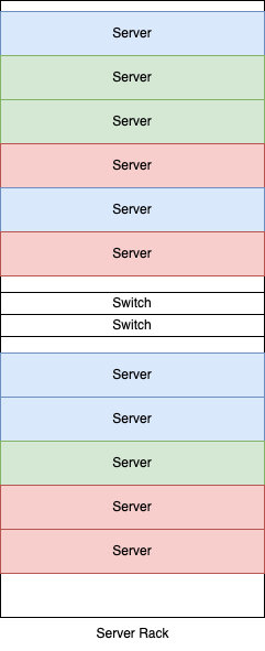
Let’s first get on the same page as far as the infrastructure that I’m referencing in this post. I’m assuming a generic, BGP-driven leaf/spine network architecture. Meaning a switch or pair of switches in each rack that are back-hauled to a centralized set of spine or aggregate switches. Each point-to-point in that architecture is running BGP across it. No .1q anywhere on that path. If VLANs exist, they’re kept to the rack, or transported across racks via VXLAN.
Virtual Routing and Forwarding
The first step to separate out these groups is to assign them to different VRFs in your data center network. If you’re still using L2 for your servers and terminating those into an SVI on your switches, then you put the SVIs into the VRFs. Obviously I’m a big proponent of routing from the host with things like Free Range Routing; if you’re doing that, then you put the servers’ switch ports into the VRFs instead.
Care has to be taken with the VRFs of course. You don’t want to get “VRF drunk” where you put every single server into its own VRF. You could do that, but it’d rapidly become unmanageable, and your top of rack switches would likely run out of resources. VRFs take memory, as you well know. Further, you’re going to want some sort of centralized management infrastructure for these groups of servers. Meaning your jump hosts, your admin hosts, you tools hosts, whatever. And, the best way to centralize them is to put them into their own VRF. You don’t want a spaghetti of VRFs all trying to communicate with the centralized VRF; better to have a few of them versus hundreds or thousands of them (if that’s even possible!)
An Arista configuration might look like:
vrf instance Blue
!
vrf instance Green
!
vrf instance Red
!
Ethernet 3/1
 vrf Blue
!
Ethernet 4/1
 vrf Green
!
Ethernet 5/1
 vrf Red
Separation: At the Rack or at the Server?
Another assumption this post is making is that your data center server deployments are automated as is the configuration of the network devices. Given that, where do we create the separation barrier in the data center? Do we say that a whole rack of servers is in a group and therefore a VRF? That’s certainly possible, but we can go much more granular than that. In fact, right down to the server. Remember that we’re separating these groups out using VRFs, and without specific configuration on the top of rack switches: one VRF absolutely and positively can not talk to another VRF. The routing and forwarding between them doesn’t exist. That means you absolutely can have a rack of servers broken up into different groups (VRFs).
The reason I mentioned automation at the beginning of this section is that you might want to make these server-to-group assignments dynamic. What if the customer using the server in rack 10 finishes and no longer needs it, but some other customer does? Well, your network automation can reassign the ports to the proper group, while your server automation re-paves the host and gets it ready for its new role.
Connecting The Racks: EVPN and VXLAN
Sticking with our example from above, you’ve broken your racks up into different VRFs by assigning your servers into the red, green, or blue groups. But recall earlier that I suggested that you not get too out of control with the VRF assignments? Well if you don’t do anything with the network that these servers are connected to, you’re going to have three independent VRFs per rack. The servers in the green group in one rack will NOT be able to communicate with any of the servers in that group in any other rack. What you need to do is use VXLAN to create a tunnel between the switches in the two racks. Once you do that, the green servers in one can talk to the green servers in another, assuming you’re also allowing that from a security perspective.
As it turns out, this is very simple to do with switches from any of the big vendors. They all support an EVPN-driven VXLAN data plane based on L2 or L3. In this case, we want L3 for that connecting of the racks. Usually, you need to define VNIs for the VRFs, add the VRFs to the EVPN configuration section of the switch, and then assign route-target imports and exports so that the VRFs on that switch can talk to the appropriate VRFs on any other switch.
If we stick with Arista, that might looks something like:
interface Vxlan1
   vxlan source-interface Loopback0
   vxlan udp-port 4789
   vxlan vrf Blue vni 1000100
   vxlan vrf Green vni 1000200
   vxlan vrf Red vni 1000300
!
router bgp 65000
   !
   vrf Blue
      route-target import evpn 65000:100
      route-target export evpn 65000:100
      redistribute connected
   !
   vrf Green
      route-target import evpn 65000:200
      route-target export evpn 65000:200
      redistribute connected
   !
   vrf Red
      route-target import evpn 65000:300
      route-target export evpn 65000:300
      redistribute connected
   !
What that does, in effect, is create a communication bus for each of the groups, and those busses stretch across all of your participating racks.
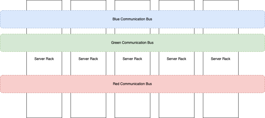
Now, servers in the Green group in any rack have a network path between them. The same with the servers in the Blue and Red groups. But at no point can any server in the Green group talk to server in the other two groups. The path between them just doesn’t exist at all, and can’t be forced or hacked (unless the network devices are broken into, but that’s a whole new problem).
Control Servers
If you’ve centralized your control, jump, tools, etc servers into a fourth group using our above example, you’re going to want a way for them to communicate with servers in the other three. Fortunately EVPN and VXLAN make that possible, but care will have to be taken when doing this. It might look like this, including some of the previous config example:
interface Vxlan1
   vxlan source-interface Loopback0
   vxlan udp-port 4789
   vxlan vrf Blue vni 1000100
   vxlan vrf Green vni 1000200
   vxlan vrf Red vni 1000300
   vxlan vrf Control vni 1001000
!
router bgp 65000
   !
   vrf Blue
      route-target import evpn 65000:1000
      route-target import evpn 65000:100
      route-target export evpn 65000:100
      redistribute connected
   !
   vrf Green
      route-target import evpn 65000:1000
      route-target import evpn 65000:200
      route-target export evpn 65000:200
      redistribute connected
   !
   vrf Red
      route-target import evpn 65000:1000
      route-target import evpn 65000:300
      route-target export evpn 65000:300
      redistribute connected
   !
   vrf Control
      route-target import evpn 65000:300
      route-target import evpn 65000:200
      route-target import evpn 65000:100
      route-target import evpn 65000:1000
      route-target export evpn 65000:1000
      redistribute connected
   !
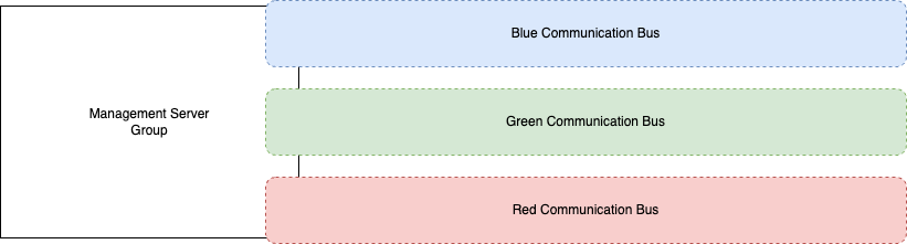
Now, with this config, we have a centralized Control VRF that has imported the route-targets of the other three VRFs. Once done, that VRF will have routing knowledge to those other VRFs. However, we have to remember that those VRFs will need knowledge on how to get back to the Control one. That’s why the extra route-target import was added to each of their stanzas.
Once done, you’ll have something that looks like this:
Security Note
It’s worth mentioning again that these imports do not come with any implicit network security. That means that each server within a group is open to any sort of mischief from another server in that group unless you add some sort of supplemental security. Be it simple filters on the switch ports or filters on the servers themselves. It also means that the servers in each group will have a back channel to the management servers; those servers will need to be locked down tight!
Ingress To and Egress From
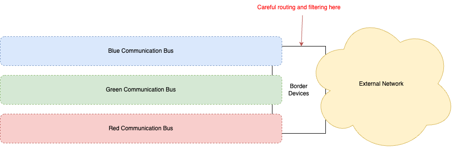
A big challenge with stuffing various workloads into VRFs is ingress and egress. How do you get packets from inside those workloads out to the rest of the world (assuming they need to get there) and vice versa? The simplest way is to terminate those aforementioned communication busses (ie: the VXLAN data planes) on a set of network devices. These can be on the border of your data center with your backbone/ISP, or inter-connects with other data centers. The network devices can stitch from VXLAN/EVPN to MPLS if you’re still using that (AND IF YOU ARE, WHYYYYYYYYYYYY?!) or they can just route the packets natively in the default VRF of the upstream network devices.
The security implications here are pretty important to pay attention to. If you decide to terminate each of the busses on the same border devices, that set of devices will have routing knowledge of each of the VRFs. Those devices can then be used as gateways between the VRFs, if you’re not careful with your route announcements. And you don’t want that to happen. So a level of network filtering (eg: ACLs, firewalls, etc) is of utmost importance.
At the Network or at the Host?
A short while ago I published this post discussing network customization and where to do it: at the network or host? In it, I made an argument that as much network customization that can be done at the server should be done there. That keeps the network infrastructure simple. It’s merely a packet pusher and nothing more. What about this? Doesn’t FRR support EVPN? Doesn’t Linux support VXLAN at the kernel level? The answer is “Yes” to both of those, but there’s a bit challenge with that.
Who are your customers? Who is using your servers? Are they all internal customers, also known as your co-workers? If so, yes, you could teach them how to handle all of this at the server layer and let them take care of the separation. But what if the customers are external? As in: actual customers of your company? They’re either renting/leasing bare metal from you, or you have a cloud of some sort and they’re running VMs on the hypervisors that you’re managing? The security risks here are rather large. You probably don’t want a machine that has external customer workloads on it having direct access to your EVPN control plane. If, for instance, that machine is a hypervisor with customer VMs on it and one of them manages to “jailbreak” out of their VM, they’ll have control of the hypervisor. And should that hypervisor be participating in the EVPN control plane, they could easily begin injecting routes into that control plane (like, say, 0.0.0.0/0) and bring your data center down.
There’s a solution to this one, though. Recall at the very beginning of my last post I mentioned the NVidia Bluefield DPUs? That’s exactly why I’m experimenting with them. More to come.