[toc]
Introduction and Purpose
Introduction
Almost three years ago, I wrote this long and detailed post about building a VXLAN-enabled virtual lab on a KVM hypervisor, using Arista’s vEOS image. Prior to that, I also wrote up this post regarding the ideas around using VXLAN for spanning L2 across an L3 infrastructure. In the second post, I wrote about the configuration challenges of static, unicast VXLAN configuration:
Further, VXLAN’s primary benefit is also a potential drawback: you have to manually configure each tunnel end point to mesh it with the rest of them. Vendors such as Arista provide a way to do that automatically using their services. Or the network team can write automation to handle the addition and subtraction of VXLAN TEPs. Neither of these are more or less advantageous, but it’s something that must be kept in mind if the idea of manually meshing a lot (eg: 120?) switches together with their upstream routers seems daunting.
Thankfully, the geeks in the networking world figured out a way to do that which involves BGP: an EVPN control plane for VXLAN.
Purpose
The purpose of this document is to describe my learning process using Cumulus Network’s OS to build a virtual seven-node network. This network will employ an EVPN control plane for VXLAN so that static unicast VXLAN configuration isn’t necessary.
EVPN Control Plane
I’m not going to spend a bunch of time discussing the ins and outs of using an EVPN control plane to handle your VXLAN deployments. There are several resources out there to learn about that from. Such as:
The idea is to use an extension to BGP to, essentially, announce L2 MAC addresses via BGP. I’m vastly over-simplifying the definition, but that’s basically what it is. As each leaf node forms an L2VPN EVPN peer with the upstream spines, it’ll begin participating in the control plane, form VTEPs with other leafs, and switch Ethernet frames between them using the spines. No manual unicast VTEPs need to be created.
Doing This With Cumulus
I spent a considerable amount of time learning about this concept at my previous role at Verisign. At that point in time, Cisco’s Nexus 7K and 9K platforms had a fairly mature and easy to configure EVPN control plane for VXLAN. Since then, however, I’ve not had much of an opportunity to deploy or test it out on other vendors’ switches and routers. But lately, I’ve turned my attention towards Cumulus Network’s Linux OS for white box switches. Thankfully, Cumulus has virtual versions of their OS available for most hypervisors out there including VMWare, KVM, and VirtualBox. The rest of this document will focus on Cumulus’ configuration in a virtual environment.
VirtualBox Environment
You’ll recall from my previous entries that I had a Linux KVM server running specifically for these sorts of labs and education. I attempted to use the same box 3 years later but it appears the PS in the server is dead. The box will not power on, and after connecting the PS to a PS tester, I saw that it was not delivering +12V. Which is a bit of a problem. Power supplies aren’t expensive, but I just don’t have an extra one handy. So instead of waiting for one to ship, I decided to attempt to do this on VirtualBox on my Mac laptop.
VM Connections
In order for this to work properly, the hypervisor in question has to allow VMs to be connected, virtually, together. Fortunately, VirtualBox offers that flexibility when you configure each VM’s network adapters. As an example, I have one of my spines here, router1. And you can see that Network Adapter 2 is attached to an “Internal Network” that I’ve named “intnet-r1-sw1”.
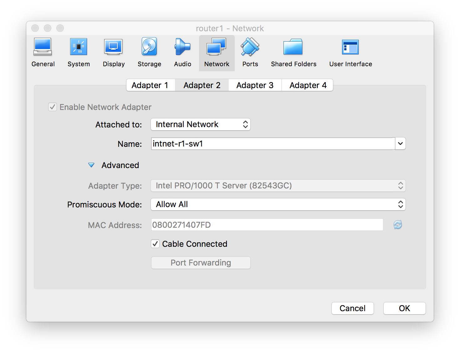
Now when I create the VM for switch1, one of its interfaces will be on that exact, same internal network. And when the VMs are both running, they’ll be virtually directly connected together.
A Note About VirtualBox and Cumulus
The Cumulus virtual OS comes ready to support 8 switch ports, named swp1, swp2, … swp8. It also has an Eth0 interface which would correspond to a real switch’s management Ethernet port. However, VirtualBox only allows for 4 Network Adapters per VM. And for some reason I’ve yet to determine, it associates Adapter 1 to Cumulus’ swp4. Meaning that each VM can only actually use swp4, swp5, swp6, and swp7. Interfaces Eth0, swp1-3, and swp8 seem to be unavailable via VirtualBox.
root@router1:/etc/frr# ifconfig swp5
swp5      Link encap:Ethernet  HWaddr 08:00:27:14:07:fd
          inet6 addr: fe80::a00:27ff:fe14:7fd/64 Scope:Link
          UP BROADCAST RUNNING MULTICAST  MTU:9216  Metric:1
          RX packets:44239 errors:0 dropped:0 overruns:0 frame:0
          TX packets:36094 errors:0 dropped:0 overruns:0 carrier:0
          collisions:0 txqueuelen:1000
          RX bytes:4416338 (4.2 MiB)  TX bytes:3627783 (3.4 MiB
You can see the output from an ifconfig swp5 above. Note the HWAddr, which corresponds to Network Adapter 2 in the previous image.
This isn’t a limitation that will cause my any issues really. I don’t expect to need more than 4 connections to any given virtual network device. But the limitation and numbering will need to be kept in mind.
“Physical” Layout
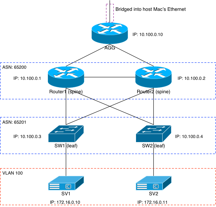
The above image shows how the virtual “physical” layout of the switches and servers is configured and connected. I’ll get into some of the important bits of each layer in this section. The basic idea was to have a simple two-leaf/two-spine architecture with a sever on each leaf, and all topped off with an aggregate router. We’ll start top down.
Agg Router
The agg router’s job is pretty simple: aggregate the IP knowledge of the entire virtual environment and provide a single gateway into and out of it. The VM configuration for the agg router is a bit different than the rest of the VMs; specifically its first interface swp4. I needed an IP path to get into and out of the environment so that I could more easily configure the VMs, as well as test to make sure the architecture works. To that end, the agg router’s swp4 (remember that’s the VM’s first interface according to VirtualBox) is actually bridged with my laptop’s en0 wireless interface.

This configuration allows my Mac, along with anything else on my private wireless network at home, to get to the agg router’s swp4 interface. The /etc/network/interface file on the agg router looks like this:
# The loopback network interface
auto lo
iface lo inet loopback
    address 10.100.0.10/32

auto swp4
iface swp4 inet dhcp

auto swp5
iface swp5
    address 10.0.3.0/31

auto swp6
iface swp6
    address 10.0.3.2/31
Since swp4 is trying to DHCP out for an IP and it’s bridged to my internal wireless network, it gets one. In fact if we look at the Cumulus CLI command net show interfaces, we see:
# net show interfa
State  Name  Spd  MTU    Mode          LLDP                  Summary
-----  ----  ---  -----  ------------  --------------------  --------------------------
UP     lo    N/A  65536  Loopback                            IP: 127.0.0.1/8
       lo                                                    IP: 10.100.0.10/32
       lo                                                    IP: ::1/128
UP     swp4  1G   1500   Interface/L3  livingroom-sw0 (gi4)  IP: 192.168.10.80/24(DHCP)
UP     swp5  1G   1500   Interface/L3  router1 (swp7)        IP: 10.0.3.0/31
UP     swp6  1G   1500   Interface/L3  router2 (swp7)        IP: 10.0.3.2/31
A few things to point out here:
- Cumulus interfaces all have LLDP running by default. You can see that in the “LLDP” column of the output. The agg router has 2 other Cumulus devices hanging off of it on swp5 and 6. But swp4 sees a different device: the Cisco switch in my living room (which is what my WAP is connected to).
- Interface swp4 did, in fact, pick up a DHCP IP of 192.168.10.80/24
- Each of the other configured interfaces have static IPs on them.
Cumulus and Unnumbered Interfaces
We’ll see later that Cumulus does support unnumbered interfaces. Which, if you’ll pardon the editorial momentarily: is pretty fricken cool. It allows you to just tell Cumulus, “Hey, go ahead and form a BGP peer on that interface” without pre-assigning an IPv4 IP on it. It uses the IPv6 link-local address to do so, and once the BGP peer is formed, IPv4 and IPv6 prefixes will be exchanged if desired. All automatically.
But in this case, I wanted to treat the agg router as something that isn’t a Cumulus. I’m imagining a big pair of agg routers in a data center or something like that; likely from another vendor. With that, I decided to statically configure the IP addresses on the interfaces to make it seem more generic.
IP Connectivity With Host Mac
With the aforementioned DHCP IP of 192.168.10.80, the agg router should be reachable from the host Mac. Let’s check:
deadshot# ping 192.168.10.80
PING 192.168.10.80 (192.168.10.80): 56 data bytes
64 bytes from 192.168.10.80: icmp_seq=0 ttl=64 time=0.274 ms
64 bytes from 192.168.10.80: icmp_seq=1 ttl=64 time=0.318 ms
64 bytes from 192.168.10.80: icmp_seq=2 ttl=64 time=0.222 ms
64 bytes from 192.168.10.80: icmp_seq=3 ttl=64 time=0.306 ms
^C
--- 192.168.10.80 ping statistics ---
4 packets transmitted, 4 packets received, 0.0% packet loss
round-trip min/avg/max/stddev = 0.222/0.280/0.318/0.037 ms
Success. We’ll need some host-based static routes on the Mac if we’re going to get into that network beyond the agg router’s swp4 interface. With that:
deadshot# route add -net 10.0.0.0/8 192.168.10.80
add net 10.0.0.0: gateway 192.168.10.80
deadshot# route add -net 172.16.0.0/12 192.168.10.80
add net 172.16.0.0: gateway 192.168.10.80
Can we get to the loopback 10.100.0.10?
deadshot# telnet 10.100.0.10 22
Trying 10.100.0.10...
Connected to 10.100.0.10.
Escape character is '^]'.
SSH-2.0-OpenSSH_6.7p1 Debian-5+deb8u4
Yep. Success. Being able to ssh into and out of the VMs will make configuration much easier. The VM console window on VirtualBox is a bit clumsy.
BGP Config
In order to get BGP running on Cumulus, you have to make sure that both zebra and bgpd are running. This is handled in the file /etc/frr/daemons. Make sure these two lines says “yes”:
zebra=yes
bgpd=yes
The rest of the routing config is handled in the file /etc/frr/frr.conf. Alternatively, you can use zebra’s vtysh command to start a more comfortable and familiar CLI for configuration. But I’m going to focus on making file changes and restarting daemons in this blog. The agg router’s frr.conf file looks like:
# default to using syslog. /etc/rsyslog.d/45-frr.conf places the log
# in /var/log/frr/frr.log
log syslog informational

router bgp 65210
bgp router-id 10.100.0.10
redistribute connected
!
neighbor spine peer-group
neighbor spine remote-as external
neighbor spine capability extended-nexthop
neighbor spine default-originate
!
neighbor swp5 interface peer-group spine
neighbor swp6 interface peer-group spine
Anyone familiar with Cisco, Arista, or other similar BGP configurations will feel pretty at-home with this. Except for the last two lines: they’re part of what make the Cumulus configuration so simple and flexible. Just above those two lines, I set up a simple “spine” peer-group with various properties. Most notable it’s an EBGP peer and the agg will be originating a default to the spines.
The two neighbor statements just tell the Cumulus router to form a BGP peer with whatever’s connected to those interfaces, and put the new neighbors in the “spine” peer group. Ridiculously easy.
Once these files are edited, a simple service frr restart command from the Linux CLI gets the ball rolling.
Spines (Router 1 and Router 2)
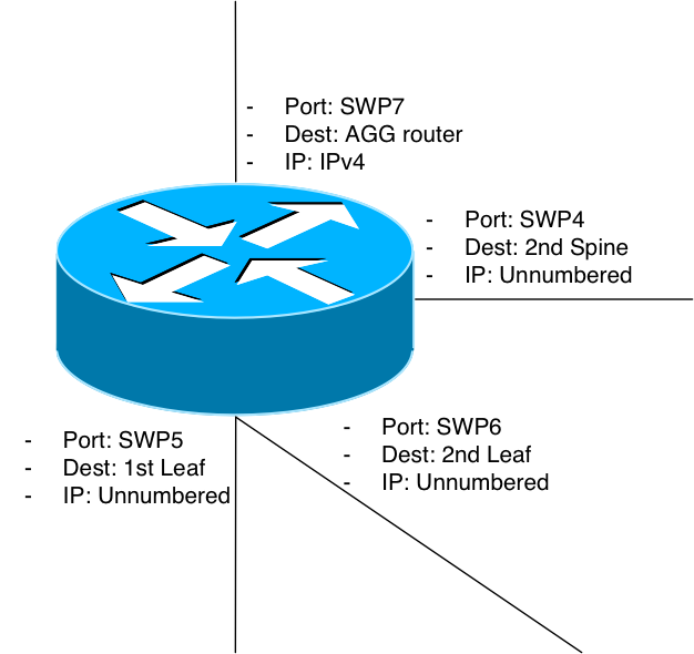
The image above shows how Router 1 is connected up; Router 2 is identical. Port swp7 is the uplink port to the previously-described agg router. Remember that although in this lab the agg router is a Cumulus device, I’m treating it as if it weren’t. So there’s an IPv4 address on the interface connected to the agg. The other 3 interfaces are unnumbered. Here’s what the /etc/network/interfaces file looks like:
# The loopback network interface
auto lo
iface lo inet loopback
    address 10.100.0.1/32

# The primary network interface
#auto eth0
#iface eth0 inet dhcp

auto swp4
iface swp4
    mtu 9216

auto swp5
iface swp5
    mtu 9216

auto swp6
iface swp6
    mtu 9216

auto swp7
iface swp7
    address 10.0.3.1/31
Pretty simple stuff. I set IP addresses on the loopback interface as well as port swp7. The other three aren’t numbered; they just have a jumbo MTU set on them. I did that because VXLAN is an overlay, and that may require packets larger than 1500 bytes.
# net show inter
State  Name      Spd  MTU    Mode           LLDP            Summary
-----  --------  ---  -----  -------------  --------------  ------------------
UP     lo        N/A  65536  Loopback                       IP: 127.0.0.1/8
       lo                                                   IP: 10.100.0.1/32
       lo                                                   IP: ::1/128
UP     swp4      1G   9216   NotConfigured  router2 (swp4)
UP     swp5      1G   9216   NotConfigured  sw1 (swp4)
UP     swp6      1G   9216   NotConfigured  sw2 (swp4)
UP     swp7      1G   1500   Interface/L3   agg (swp5)      IP: 10.0.3.1/31
The lldp clearly shows that swp4 is connected to the other spine, swp5 and 6 are connected to leaf1 and 2, and swp7 is the uplink to the agg router.
BGP Config
How about the BGP config on the spines? It’s a bit more involved than the agg, but not by much:
router bgp 65200
	bgp router-id 10.100.0.1
	bgp bestpath as-path multipath-relax
!
	neighbor swp7 interface
	neighbor swp7 remote-as external
!
	neighbor swp4 interface
	neighbor swp4 remote-as internal
	neighbor swp4 next-hop-self
!
	neighbor leaf peer-group
	neighbor leaf remote-as external
!
	neighbor swp5 interface peer-group leaf
	neighbor swp6 interface peer-group leaf
!
! IPv4
	address-family ipv4 unicast
		redistribute connected
		neighbor leaf activate
	exit-address-family
The neighbor on swp7 is our agg router and it’s an external (eBGP) peer. The neighbor on swp4 is the other spine so the peering an iBGP one. Then I’ve set up a simple peer group for the leaves; they’re just another eBGP peer. Assign them, activate them, and redistribute the connected into BGP. In the output below, you’ll see that the leaves are already configured and routing via BGP. We’ll get into that in the next section. But for now:
# net show bgp ipv4 unicast sum
BGP router identifier 10.100.0.1, local AS number 65200 vrf-id 0
BGP table version 17
RIB entries 17, using 2584 bytes of memory
Peers 4, using 77 KiB of memory
Peer groups 1, using 64 bytes of memory

Neighbor        V         AS MsgRcvd MsgSent   TblVer  InQ OutQ  Up/Down State/PfxRcd
sw1(swp5)       4      65201   17519   17521        0    0    0 14:35:07            2
sw2(swp6)       4      65201   17518   17521        0    0    0 14:35:07            2
router2(swp4)   4      65200   17507   17507        0    0    0 14:35:07            8
agg(swp7)       4      65210   17495   17500        0    0    0 01:09:20            5
And let’s make sure we’re hearing a 0/0 from the agg:
# net show route 0.0.0.0
RIB entry for 0.0.0.0
=====================
Routing entry for 0.0.0.0/0
Known via "bgp", distance 20, metric 0, best
Last update 01:10:40 ago
* 10.0.3.0, via swp7


FIB entry for 0.0.0.0
=====================
default via 10.0.3.0 dev swp7 proto bgp metric 20
Yep. Can we get to routers 1 and 2 via IP, from the host Mac?
deadshot# telnet 10.100.0.1 22
Trying 10.100.0.1...
Connected to 10.100.0.1.
Escape character is '^]'.
SSH-2.0-OpenSSH_6.7p1 Debian-5+deb8u4
Success.
Leaves (Switch 1 and Switch 2)
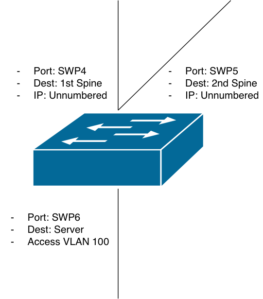
You can see how the leaf is connected, based on the diagram above. Each is identical. The first two interfaces are unnumbered. The third is a bit different. Port swp6 will be what our server connects to. We’ll put the server on VLAN100 via an access port on the leaf. Some of the VLAN configuration will show up a bit later as we discuss EVPN and VXLAN. But for now, the /etc/network/interfaces file:
# The loopback network interface
auto lo
iface lo inet loopback
    # The primary network interface
    address 10.100.0.3/32

# The primary network interface
#auto eth0
#iface eth0 inet dhcp

auto swp4
iface swp4
    mtu 9216

auto swp5
iface swp5
    mtu 9216

auto swp6
iface swp6
    bridge-access 100

auto bridge
iface bridge
    bridge-ports swp6
    bridge-vids 100
    bridge-vlan-aware yes
Again, swp4 and 5 are unnumbered. Port swp6 has been set up with bridge access to VLAN 100. And we need a bridge port configured with VLAN configuration as shown. Missing is the SVI interface for VLAN 100. In other words: the server that comes up on VLAN 100 won’t have ingress/egress yet. We’ll get to that a bit later.
BGP Config
Let’s show the BGP configuration on the leaf, even though we know it’s working from the previous section:
router bgp 65201
 bgp router-id 10.100.0.3
 bgp bestpath as-path multipath-relax
 neighbor spine peer-group
 neighbor spine remote-as external
 neighbor swp4 interface peer-group spine
 neighbor swp5 interface peer-group spine
 !
 address-family ipv4 unicast
  redistribute connected
  neighbor spine allowas-in origin
 exit-address-family
 !
Simple and easy, and very like the upstream spines. Interface-peer via ports swp4 and 5, and do so unnumbered. One small change is that we need to allow our local ASN in. Each leaf is in ASN 65201; if any leaf announces something via IPv4 that another leaf needs to hear for some reason, we have to allow ASN 65201 in. This will, again, become a bit more important in a moment.
# net show bgp ipv4 uni sum
BGP router identifier 10.100.0.3, local AS number 65201 vrf-id 0
BGP table version 19
RIB entries 17, using 2584 bytes of memory
Peers 2, using 39 KiB of memory
Peer groups 1, using 64 bytes of memory

Neighbor        V         AS MsgRcvd MsgSent   TblVer  InQ OutQ  Up/Down State/PfxRcd
router1(swp4)   4      65200   17855   17854        0    0    0 14:51:47           10
router2(swp5)   4      65200   17856   17857        0    0    0 14:51:51           10
# net show route 0.0.0.0
RIB entry for 0.0.0.0
=====================
Routing entry for 0.0.0.0/0
  Known via "bgp", distance 20, metric 0, best
  Last update 14:52:03 ago
  * fe80::a00:27ff:fe14:7fd, via swp4
  * fe80::a00:27ff:fefd:b2b0, via swp5


FIB entry for 0.0.0.0
=====================
default  proto bgp  metric 20
	nexthop via 169.254.0.1  dev swp4 weight 1 onlink
	nexthop via 169.254.0.1  dev swp5 weight 1 onlink
And here you can see what happens when you use unnumbered BGP. The show route 0.0.0.0 command returns both spines. But they’re IPv6 addresses. More specifically, they’re link-local IPv6 addresses. Ultimately, that’s how the unnumbered trick is working with Cumulus. The nexthop is an IPv4 address of 169.254.0.1, but the interfaces are clearly two different ones.
Pretty cool, huh?
And let’s do the same SSH test as before, from the host Mac:
deadshot# telnet 10.100.0.3 22
Trying 10.100.0.3...
Connected to 10.100.0.3.
Escape character is '^]'.
SSH-2.0-OpenSSH_6.7p1 Debian-5+deb8u4
Done.
EVPN And VXLAN
I’m going to jump into the EVPN and VXLAN configurations of the four network devices in this section. Before I do that, I’d like to address a missing layer in the network and why I didn’t build it. This is going to seem like a tangent, but it’ll make sense a bit later. Stay with me.
The Case Against: The Service Leaf
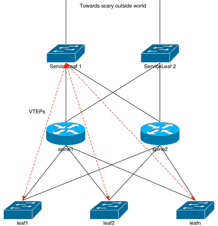
I hate to use the word “traditional” when describing the diagram above, because that word generally indicates something that’s been around for a while. The design in the previous image is something that a certain network company, we’ll call them Company A, developed a few years ago. They coined the phrase “Leaf/Spine” network architecture and the industry quickly adopted the phrase. I can assure you: they weren’t the first folks to actually come up with the architecture; I was building networking like that back in the mid 1990s. Long before Company A was actually a thing.
Regardless of that, one of the key points in the design, which differs from mine, is the “Service Leaf” layer. Some companies call it the service leaf, others the border leaf, etc. I call it: a waste of hardware and a compromise in the network design that shouldn’t be made. Let’s dive into that.
Company A might tell you that the Service Leaf exists to keep the configuration on the Spines as simple as possible. They don’t want the Spines actively participating in VXLAN; just routing BGP packets to and from each leaf. The service leaf’s job is to form VTEPs with all of the tenant leaves, and provide a routed path into and out of the entire network. It’s to the service leaves that an EBGP peer would come in, either from an data center aggregation router, or an external ISP, or whatever. The service leaves are the same make and model as the tenant leaves, and that means they can actually perform VXLAN routing.
That part is key. It’s because of that, and not to keep the “spines simple”, that the service leaf exists. Company A’s first attempt at a big, dense, chassis-based switch didn’t have VXLAN routing in hardware. They couldn’t do it. Their top-of-rack switches supported it, easily. But the chassis didn’t. They didn’t have the appropriate merchant silicon on the line cards in the chassis. So: no VXLAN routing at first.
“Keep the spine config simple?” Or is it “We can’t do it on the spine?” I know which one I’m putting my money on.
The problem with the design is: extra layers of hardware for a packet to flow through. I’m thinking of an entire system. And entire data center. I’m not thinking about the little corner of the data center that has VXLAN running. End to end. The overall reliability of a system decreases with every device a packet has to flow through. It is important, in my opinion, that the network architecture reflects this reliability issue as best it can. That means: where ever it makes sense and where ever you can: remove network hardware. Don’t add it!
This is why I’m adamantly against the service leaf layer. Today, spine architectures are all made from the same merchant silicon that are in the switches. They can easily handle VXLAN routing. So: do it there!
Now then…
Spine Changes
Now that we have the L3 underpinning, we can add the overlay and control plane on top of it. This is pretty easy on Cumulus. No changes need to be made to the /etc/network/interfaces file.
Changes to /etc/frr/frr.conf
!
! EVPN config

address-family l2vpn evpn
    neighbor leaf activate
!
exit-address-family
A simple l2vpn evpn address family needs to be added, and the same leaf peer-group that was previously defined needs to be activated. And that’s it. Just perform a service frr restart and the spines are ready to go.
Leaf Changes
The changes at the switch layer are a bit more complicated because we need to the VLAN 100 SVI configured, VLAN 100 added into VXLAN, and then the EVPN control plane configured.
Changes to /etc/interfaces
auto bridge
iface bridge
    bridge-ports swp6 vni10100
    bridge-vids 100
    bridge-vlan-aware yes

auto vni10100
iface vni10100
    bridge-access 100
    bridge-arp-nd-suppress on
    bridge-learning off
    mstpctl-bpduguard yes
    mstpctl-portbpdufilter yes
    mtu 9000
    vxlan-id 10100
    vxlan-local-tunnelip 10.100.0.3

auto vlan100
iface vlan100
    address 172.16.0.2/24
    vlan-id 100
    vlan-raw-device bridge
    address-virtual 44:39:39:FF:40:94 172.16.0.1/24
Here I’ve added two new interfaces: vni10100 and vlan100. The later is the SVI for VLAN100. It’s what will provided the routed path into and out of VLAN 100. Pretty simple. But let’s look at it a bit more closely: we see it has an address of .2, but a virtual address of .1 along with a MAC address set. That same virtual address and MAC need to be set on the VLAN 100 interface on switch 2. Like previous VXLAN configurations, this is how servers can be moved around on different switches in VLAN 100, and retain their same IP and default route. Each switch participating in VXLAN routing for VLAN 100 will need that virtual address line.
The vni10100 interface is what gets VXLAN going. The important bits are that it’s part of VLAN 100, has a VXLAN ID of 10100, and is using the switch’s loopback IP as its tunnel end point.
And finally to complete it, we add the new vni10100 interface to the bridge interface.
The command ifreload -a kicks all of the new interface information into gear.
root@sw1:/home/jvp# net show int
State  Name        Spd  MTU    Mode           LLDP            Summary
-----  ----------  ---  -----  -------------  --------------  ------------------
UP     lo          N/A  65536  Loopback                       IP: 127.0.0.1/8
       lo                                                     IP: 10.100.0.3/32
       lo                                                     IP: ::1/128
UP     swp4        1G   9216   NotConfigured  router1 (swp5)
UP     swp5        1G   9216   NotConfigured  router2 (swp5)
UP     swp6        1G   1500   Access/L2      sv1 (swp4)      Master: bridge(UP)
UP     bridge      N/A  1500   Bridge/L2
UP     vlan100     N/A  1500   Interface/L3                   IP: 172.16.0.2/24
UP     vlan100-v0  N/A  1500   Interface/L3                   IP: 172.16.0.1/24
UP     vni10100    N/A  9000   Access/L2                      Master: bridge(UP)
Of course, we have our server connected to swp6, which we haven’t been able to get to yet. Can we?
root@sw1:/home/jvp# ping 172.16.0.10
PING 172.16.0.10 (172.16.0.10) 56(84) bytes of data.
64 bytes from 172.16.0.10: icmp_seq=1 ttl=64 time=0.000 ms
64 bytes from 172.16.0.10: icmp_seq=2 ttl=64 time=0.362 ms
64 bytes from 172.16.0.10: icmp_seq=3 ttl=64 time=0.291 ms
64 bytes from 172.16.0.10: icmp_seq=4 ttl=64 time=0.295 ms
^C
--- 172.16.0.10 ping statistics ---
4 packets transmitted, 4 received, 0% packet loss, time 3002ms
rtt min/avg/max/mdev = 0.000/0.237/0.362/0.139 ms
Yep.
We perform the same changes to the interfaces file on switch 2, and we can ping the server locally attached there. The only difference is the real IP we assign to VLAN 100: make that 172.16.0.3/24.
root@sw2:/home/jvp# net show int
State  Name        Spd  MTU    Mode           LLDP            Summary
-----  ----------  ---  -----  -------------  --------------  ------------------
UP     lo          N/A  65536  Loopback                       IP: 127.0.0.1/8
       lo                                                     IP: 10.100.0.4/32
       lo                                                     IP: ::1/128
UP     swp4        1G   9216   NotConfigured  router1 (swp6)
UP     swp5        1G   9216   NotConfigured  router2 (swp6)
UP     swp6        1G   1500   Access/L2      sv2 (swp4)      Master: bridge(UP)
UP     bridge      N/A  1500   Bridge/L2
UP     vlan100     N/A  1500   Interface/L3                   IP: 172.16.0.3/24
UP     vlan100-v0  N/A  1500   Interface/L3                   IP: 172.16.0.1/24
UP     vni10100    N/A  9000   Access/L2                      Master: bridge(UP)

root@sw2:/home/jvp# ping 172.16.0.11
PING 172.16.0.11 (172.16.0.11) 56(84) bytes of data.
64 bytes from 172.16.0.11: icmp_seq=1 ttl=64 time=0.022 ms
64 bytes from 172.16.0.11: icmp_seq=2 ttl=64 time=0.392 ms
64 bytes from 172.16.0.11: icmp_seq=3 ttl=64 time=0.374 ms

--- 172.16.0.11 ping statistics ---
3 packets transmitted, 3 received, 0% packet loss, time 2002ms
rtt min/avg/max/mdev = 0.022/0.262/0.392/0.171 ms
Changes to /etc/frr/frr.conf
The changes to the frr.conf file are pretty simple, or so I thought…
address-family l2vpn evpn
    neighbor spine activate
    advertise-all-vni
exit-address-family
Activate the spine peer-group, and make sure to advertise any and all VNIs. In my case, VNI10100 would be the only one. But I wasn’t seeing any EVPN announcements. The only thing switch 1 saw was itself. Hm.
root@sw1:/home/jvp# net show bgp evpn route vni 10100
BGP table version is 20, local router ID is 10.100.0.3
Status codes: s suppressed, d damped, h history, * valid, > best, i - internal
Origin codes: i - IGP, e - EGP, ? - incomplete
EVPN type-2 prefix: [2]:[ESI]:[EthTag]:[MAClen]:[MAC]:[IPlen]:[IP]
EVPN type-3 prefix: [3]:[EthTag]:[IPlen]:[OrigIP]
EVPN type-5 prefix: [5]:[ESI]:[EthTag]:[IPlen]:[IP]

   Network          Next Hop            Metric LocPrf Weight Path
*> [2]:[0]:[0]:[48]:[08:00:27:36:62:99]
                    10.100.0.3                         32768 i
*> [2]:[0]:[0]:[48]:[08:00:27:36:62:99]:[32]:[172.16.0.10]
                    10.100.0.3                         32768 i
*> [2]:[0]:[0]:[48]:[08:00:27:36:62:99]:[128]:[fe80::a00:27ff:fe36:6299]
                    10.100.0.3                         32768 i
*> [3]:[0]:[32]:[10.100.0.3]
                    10.100.0.3                         32768 i
Displayed 4 prefixes (4 paths)
The switch isn’t seeing the MAC address announcement from switch 2. What if I check one of the spines?
root@router1:/etc/network# net show bgp evpn route
BGP table version is 12, local router ID is 10.100.0.1
Status codes: s suppressed, d damped, h history, * valid, > best, i - internal
Origin codes: i - IGP, e - EGP, ? - incomplete
EVPN type-2 prefix: [2]:[ESI]:[EthTag]:[MAClen]:[MAC]:[IPlen]:[IP]
EVPN type-3 prefix: [3]:[EthTag]:[IPlen]:[OrigIP]
EVPN type-5 prefix: [5]:[ESI]:[EthTag]:[IPlen]:[IP]

   Network          Next Hop            Metric LocPrf Weight Path
Route Distinguisher: 10.100.0.3:2
*> [2]:[0]:[0]:[48]:[08:00:27:36:62:99]
                    10.100.0.3                             0 65201 i
*> [2]:[0]:[0]:[48]:[08:00:27:36:62:99]:[32]:[172.16.0.10]
                    10.100.0.3                             0 65201 i
*> [2]:[0]:[0]:[48]:[08:00:27:36:62:99]:[128]:[fe80::a00:27ff:fe36:6299]
                    10.100.0.3                             0 65201 i
*> [3]:[0]:[32]:[10.100.0.3]
                    10.100.0.3                             0 65201 i
Route Distinguisher: 10.100.0.4:2
*> [2]:[0]:[0]:[48]:[08:00:27:36:f2:4e]
                    10.100.0.4                             0 65201 i
*> [2]:[0]:[0]:[48]:[08:00:27:36:f2:4e]:[32]:[172.16.0.11]
                    10.100.0.4                             0 65201 i
*> [2]:[0]:[0]:[48]:[08:00:27:36:f2:4e]:[128]:[fe80::a00:27ff:fe36:f24e]
                    10.100.0.4                             0 65201 i
*> [3]:[0]:[32]:[10.100.0.4]
                    10.100.0.4                             0 65201 i

Displayed 8 prefixes (8 paths)
The spine sees announcements from both leaves. But switch 1 isn’t hearing… or wait… maybe it’s not accepting the announcements from switch 2!? It turns out that’s exactly what the problem was. It was the output from the spine that gave me the hint I needed: the ASN of 65201 attached to the announcements. The switches were set up to allow their own ASNs in in the IPv4 family but not the l2vpn evpn family!
Derp.
address-family l2vpn evpn
   neighbor spine activate
   neighbor spine allowas-in origin
   advertise-all-vni
exit-address-family
And now:
root@sw1:/home/jvp# net show bgp evpn route vni 10100
BGP table version is 20, local router ID is 10.100.0.3
Status codes: s suppressed, d damped, h history, * valid, > best, i - internal
Origin codes: i - IGP, e - EGP, ? - incomplete
EVPN type-2 prefix: [2]:[ESI]:[EthTag]:[MAClen]:[MAC]:[IPlen]:[IP]
EVPN type-3 prefix: [3]:[EthTag]:[IPlen]:[OrigIP]
EVPN type-5 prefix: [5]:[ESI]:[EthTag]:[IPlen]:[IP]

   Network          Next Hop            Metric LocPrf Weight Path
*> [2]:[0]:[0]:[48]:[08:00:27:36:62:99]
                    10.100.0.3                         32768 i
*> [2]:[0]:[0]:[48]:[08:00:27:36:62:99]:[32]:[172.16.0.10]
                    10.100.0.3                         32768 i
*> [2]:[0]:[0]:[48]:[08:00:27:36:62:99]:[128]:[fe80::a00:27ff:fe36:6299]
                    10.100.0.3                         32768 i
*  [2]:[0]:[0]:[48]:[08:00:27:36:f2:4e]
                    10.100.0.4                             0 65200 65201 i
*> [2]:[0]:[0]:[48]:[08:00:27:36:f2:4e]
                    10.100.0.4                             0 65200 65201 i
*  [2]:[0]:[0]:[48]:[08:00:27:36:f2:4e]:[32]:[172.16.0.11]
                    10.100.0.4                             0 65200 65201 i
*> [2]:[0]:[0]:[48]:[08:00:27:36:f2:4e]:[32]:[172.16.0.11]
                    10.100.0.4                             0 65200 65201 i
*  [2]:[0]:[0]:[48]:[08:00:27:36:f2:4e]:[128]:[fe80::a00:27ff:fe36:f24e]
                    10.100.0.4                             0 65200 65201 i
*> [2]:[0]:[0]:[48]:[08:00:27:36:f2:4e]:[128]:[fe80::a00:27ff:fe36:f24e]
                    10.100.0.4                             0 65200 65201 i
*> [3]:[0]:[32]:[10.100.0.3]
                    10.100.0.3                         32768 i
*  [3]:[0]:[32]:[10.100.0.4]
                    10.100.0.4                             0 65200 65201 i
*> [3]:[0]:[32]:[10.100.0.4]
                    10.100.0.4                             0 65200 65201 i

Displayed 8 prefixes (12 paths)
The switches each see the servers on the other. Remember that 172.16.0.11 is on switch 2:
root@sw1:/home/jvp# ping 172.16.0.11
PING 172.16.0.11 (172.16.0.11) 56(84) bytes of data.
64 bytes from 172.16.0.11: icmp_seq=1 ttl=64 time=0.884 ms
64 bytes from 172.16.0.11: icmp_seq=2 ttl=64 time=1.06 ms
64 bytes from 172.16.0.11: icmp_seq=3 ttl=64 time=1.03 ms
64 bytes from 172.16.0.11: icmp_seq=4 ttl=64 time=1.03 ms
^C
--- 172.16.0.11 ping statistics ---
4 packets transmitted, 4 received, 0% packet loss, time 3008ms
rtt min/avg/max/mdev = 0.884/1.004/1.065/0.080 ms
root@sw1:/home/jvp# net show route 172.16.0.11
RIB entry for 172.16.0.11
=========================
Routing entry for 172.16.0.0/24
  Known via "connected", distance 0, metric 0
  Last update 16:47:43 ago
  * directly connected, vlan100-v0

Routing entry for 172.16.0.0/24
  Known via "connected", distance 0, metric 0, best
  Last update 16:47:43 ago
  * directly connected, vlan100


FIB entry for 172.16.0.11
=========================
172.16.0.0/24 dev vlan100  proto kernel  scope link  src 172.16.0.2
172.16.0.0/24 dev vlan100-v0  proto kernel  scope link  src 172.16.0.1  metric 1024
root@sw1:/home/jvp# arp -an 172.16.0.11
arp: in 4 entries no match found.
root@sw1:/home/jvp# net show evpn arp-cache vni 10100
Number of ARPs (local and remote) known for this VNI: 8
IP                        Type   MAC               Remote VTEP
fe80::a00:27ff:fe36:f24e  remote 08:00:27:36:f2:4e 10.100.0.4
172.16.0.1                local  44:39:39:ff:40:94
172.16.0.11               remote 08:00:27:36:f2:4e 10.100.0.4
172.16.0.10               local  08:00:27:36:62:99
fe80::4639:39ff:feff:4094 local  44:39:39:ff:40:94
fe80::a00:27ff:fe36:6299  local  08:00:27:36:62:99
fe80::a00:27ff:fec1:571a  local  08:00:27:c1:57:1a
172.16.0.2                local  08:00:27:c1:57:1a
Checking from the Mac:
deadshot# ping 172.16.0.10
PING 172.16.0.10 (172.16.0.10): 56 data bytes
64 bytes from 172.16.0.10: icmp_seq=0 ttl=61 time=1.253 ms
64 bytes from 172.16.0.10: icmp_seq=1 ttl=61 time=1.029 ms
64 bytes from 172.16.0.10: icmp_seq=2 ttl=61 time=1.260 ms
^C
--- 172.16.0.10 ping statistics ---
3 packets transmitted, 3 packets received, 0.0% packet loss
round-trip min/avg/max/stddev = 1.029/1.181/1.260/0.107 ms
deadshot# ping 172.16.0.11
PING 172.16.0.11 (172.16.0.11): 56 data bytes
64 bytes from 172.16.0.11: icmp_seq=0 ttl=61 time=1.091 ms
64 bytes from 172.16.0.11: icmp_seq=1 ttl=61 time=1.100 ms
64 bytes from 172.16.0.11: icmp_seq=2 ttl=61 time=1.161 ms
^C
--- 172.16.0.11 ping statistics ---
3 packets transmitted, 3 packets received, 0.0% packet loss
round-trip min/avg/max/stddev = 1.091/1.117/1.161/0.031 ms
deadshot# telnet 172.16.0.11 22
Trying 172.16.0.11...
Connected to 172.16.0.11.
Escape character is '^]'.
SSH-2.0-OpenSSH_6.7p1 Debian-5+deb8u4
I can ping both of them and get to their SSH ports. Cool.
One last check is from the servers themselves. If they’re on the same L2 broadcast domain, they’ll have ARP entries for each other. Let’s check one of the servers:
root@sv1:/home/jvp# ping 172.16.0.11
PING 172.16.0.11 (172.16.0.11) 56(84) bytes of data.
64 bytes from 172.16.0.11: icmp_seq=1 ttl=64 time=1.94 ms
64 bytes from 172.16.0.11: icmp_seq=2 ttl=64 time=1.35 ms
64 bytes from 172.16.0.11: icmp_seq=3 ttl=64 time=0.952 ms
^C
--- 172.16.0.11 ping statistics ---
3 packets transmitted, 3 received, 0% packet loss, time 2002ms
rtt min/avg/max/mdev = 0.952/1.416/1.940/0.407 ms
root@sv1:/home/jvp# arp -an
? (172.16.0.4) at 42:cd:17:09:60:b4 [ether] on swp4
? (172.16.0.2) at 08:00:27:c1:57:1a [ether] on swp4
? (172.16.0.1) at 44:39:39:ff:40:94 [ether] on swp4
? (172.16.0.11) at 08:00:27:36:f2:4e [ether] on swp4
Success.
Optimizing North-South Traffic
If I wanted to follow the “traditional” VXLAN leaf/spine architecture, I’d call myself done with the previous exercise. But: I’m not done because I don’t want to follow that architecture. The problem with the network that I have set up right now is inefficient routing to each server from off-net. I’ll explain. Ignoring the aggregation router here: the entry point into the entire network is through the spines. They know about the 172.16.0.0/24 prefix via both switches. Meaning they’ll ECMP incoming traffic that’s destined for them.
root@router1:/etc/network# net show route 172.16.0.0/24
RIB entry for 172.16.0.0/24
===========================
Routing entry for 172.16.0.0/24
  Known via "bgp", distance 20, metric 0, best
  Last update 01:10:35 ago
  * fe80::a00:27ff:fec7:fe0c, via swp5
  * fe80::a00:27ff:fed5:26e6, via swp6


FIB entry for 172.16.0.0/24
===========================
172.16.0.0/24  proto bgp  metric 20
	nexthop via 169.254.0.1  dev swp5 weight 1 onlink
	nexthop via 169.254.0.1  dev swp6 weight 1 onlink
There’s a 50% chance that the packet will come in for 172.16.0.10 and be sent to switch 1. Meaning there’s a 50% chance it’ll be sent to switch 2. If the former: that’s good. If the latter, it means switch 2 will encapsulate the packet into a VXLAN tunnel, send it back to the spines destined for switch 1. Switch 1 will decapsulate it and deliver it to the server. This works fine, but is somewhat inefficient.
And the more leaves you have, the greater the chance you have of the packet getting routed inefficiently.
This is one reason the service leaf continues to exist today: because it has VXLAN tunnels with each of the downstream leaves, it knows exactly which leaf the server is on, it encaps the packet into a VXLAN tunnel, and sends it directly to the right leaf.
VXLAN On The Spine
Doing VXLAN on the spine is the other way to solve this problem, and makes for a more efficient and reliable network architecture. It means we need to add the VLANs, bridge interfaces, and VNIs to the spines. So that has to be kept in mind: this isn’t a freebie. More configuration is necessary. But the trade-off is: less networking devices to have to manage. I think that’s a win, personally.
Changes to /etc/network/interfaces
The changes are just like what I added to the switches earlier:
auto bridge
iface bridge
    bridge-ports vni10100
    bridge-vids 100
    bridge-vlan-aware yes

auto vlan100
iface vlan100
    address 172.16.0.4/24
    vlan-id 100
    vlan-raw-device bridge

iface vni10100
    bridge-access 100
    bridge-arp-nd-suppress on
    bridge-learning off
    vxlan-id 10100
    vxlan-local-tunnelip 10.100.0.1
    mtu 9000
Reloading the interface config gets a whole new spine:
root@router1:/etc/network# net show int
State  Name      Spd  MTU    Mode           LLDP            Summary
-----  --------  ---  -----  -------------  --------------  ------------------
UP     lo        N/A  65536  Loopback                       IP: 127.0.0.1/8
       lo                                                   IP: 10.100.0.1/32
       lo                                                   IP: ::1/128
UP     swp4      1G   9216   NotConfigured  router2 (swp4)
UP     swp5      1G   9216   NotConfigured  sw1 (swp4)
UP     swp6      1G   9216   NotConfigured  sw2 (swp4)
UP     swp7      1G   1500   Interface/L3   agg (swp5)      IP: 10.0.3.1/31
UP     bridge    N/A  9000   Bridge/L2
UP     vlan100   N/A  9000   Interface/L3                   IP: 172.16.0.4/24
UP     vni10100  N/A  9000   Access/L2                      Master: bridge(UP)
And I can still ping the server in question. But the difference is: I have ARP knowledge of it now, via VXLAN!
root@router1:/etc/network# ping 172.16.0.10
PING 172.16.0.10 (172.16.0.10) 56(84) bytes of data.
64 bytes from 172.16.0.10: icmp_seq=1 ttl=64 time=0.754 ms
64 bytes from 172.16.0.10: icmp_seq=2 ttl=64 time=1.12 ms
^C
--- 172.16.0.10 ping statistics ---
2 packets transmitted, 2 received, 0% packet loss, time 1001ms
rtt min/avg/max/mdev = 0.754/0.939/1.125/0.188 ms
root@router1:/etc/network# net show route 172.16.0.10
RIB entry for 172.16.0.10
=========================
Routing entry for 172.16.0.0/24
  Known via "connected", distance 0, metric 0, best
  Last update 00:01:13 ago
  * directly connected, vlan100


FIB entry for 172.16.0.10
=========================
172.16.0.0/24 dev vlan100  proto kernel  scope link  src 172.16.0.4
root@router1:/etc/network# net show evpn arp-cache vni 10100
Number of ARPs (local and remote) known for this VNI: 6
IP                        Type   MAC               Remote VTEP
fe80::a00:27ff:fe36:f24e  remote 08:00:27:36:f2:4e 10.100.0.4
fe80::40cd:17ff:fe09:60b4 local  42:cd:17:09:60:b4
172.16.0.4                local  42:cd:17:09:60:b4
172.16.0.11               remote 08:00:27:36:f2:4e 10.100.0.4
172.16.0.10               remote 08:00:27:36:62:99 10.100.0.3
fe80::a00:27ff:fe36:6299  remote 08:00:27:36:62:99 10.100.0.3
What this means is that the packet will come into either of the spines, they’ll immediately encapsulate the packet, and send it to the appropriate VTEP. In this instance, that means switch 1.
What Else Can We Do?
If we’re very careful with L2 applications on the spines, we can do a few more things without the need for those service leaves. One “for instance” is a load balancer that may need L2 access to a bunch of the servers on various leaves. If we assume our load balancer is too stupid and incapable of participating in VXLAN and it needs L2 access, that means you have to trunk L2 to it. And that same L2 needs to be available to the servers on the leaves. So attach it to the spines on L2 trunk ports, and add those into the same VNI as the server VLAN(s). If your company has decided it needs HA load balancers (which are rarely a good idea), that means you need a contiguous L2 broadcast domain between them for their virtual default route. Again: this is easy. Connect LB1 to spine 1, LB2 to spine 2. Set up a trunk interface on each spine with the same VLAN, and then use VXLAN between the two spines to carry that L2 information. The LBs will see each other via that path, and determine which is active and which is standby. And because that virtual IP is on the same VLAN as the downstream servers, the servers will be able to use it.
HA firewalls are the same way. Again: these abominations of devices need a contiguous L2 broadcast domain so that they can figure out which firewall is active and which is standby. And again: this can easily be accomplished on the spines with careful trunking and VXLAN’ing.
Appendices
Appendix A – Spine 1 Configuration Files
/etc/network/interfaces
# The loopback network interface
auto lo
iface lo inet loopback
    address 10.100.0.1/32

auto swp4
iface swp4
    mtu 9216

auto swp5
iface swp5
    mtu 9216

auto swp6
iface swp6
    mtu 9216

auto swp7
iface swp7
    address 10.0.3.1/31
auto bridge
iface bridge
    bridge-ports vni10100
    bridge-vids 100
    bridge-vlan-aware yes

auto vlan100
iface vlan100
    address 172.16.0.4/24
    vlan-id 100
    vlan-raw-device bridge

iface vni10100
    bridge-access 100
    bridge-arp-nd-suppress on
    bridge-learning off
    vxlan-id 10100
    vxlan-local-tunnelip 10.100.0.1
    mtu 9000
/etc/frr/frr.conf
router bgp 65200
	bgp router-id 10.100.0.1
	bgp bestpath as-path multipath-relax
	redistribute connected
!
	neighbor swp7 interface
	neighbor swp7 remote-as external
	neighbor swp7 capability extended-nexthop
!
	neighbor swp4 interface
	neighbor swp4 remote-as internal
	neighbor swp4 next-hop-self
!
	neighbor leaf peer-group
	neighbor leaf remote-as external
!
	neighbor swp5 interface peer-group leaf
	neighbor swp6 interface peer-group leaf
!
! IPv4
	address-family ipv4 unicast
		redistribute connected
		neighbor leaf activate
	exit-address-family
!
! EVPN config

	address-family l2vpn evpn
		neighbor leaf activate
		neighbor swp4 activate
		advertise-all-vni
!
	exit-address-family
Appendix B – Spine 2 Configuration Files
/etc/network/interfaces
# The loopback network interface
auto lo
iface lo inet loopback
    # The primary network interface
    address 10.100.0.2/32

auto swp4
iface swp4
    mtu 9216

auto swp5
iface swp5
    mtu 9216

auto swp6
iface swp6
    mtu 9216

auto swp7
iface swp7
    address 10.0.3.3/31

auto bridge
iface bridge
    bridge-ports vni10100
    bridge-vids 100
    bridge-vlan-aware yes

auto vlan100
iface vlan100
    address 172.16.0.5/24
    vlan-id 100
    vlan-raw-device bridge

iface vni10100
    bridge-access 100
    bridge-arp-nd-suppress on
    bridge-learning off
    vxlan-id 10100
    vxlan-local-tunnelip 10.100.0.2
    mtu 9000
/etc/frr/frr.conf
router bgp 65200
        bgp router-id 10.100.0.2
        bgp bestpath as-path multipath-relax
!
        neighbor swp7 interface
        neighbor swp7 remote-as external
        neighbor swp7 capability extended-nexthop
!
        neighbor swp4 interface
        neighbor swp4 remote-as internal
        neighbor swp4 next-hop-self
!
        neighbor leaf peer-group
        neighbor leaf remote-as external
!
        neighbor swp5 interface peer-group leaf
        neighbor swp6 interface peer-group leaf
!
! IPv4
        address-family ipv4 unicast
                redistribute connected
                neighbor leaf activate
        exit-address-family
!
! EVPN config

        address-family l2vpn evpn
                neighbor leaf activate
                neighbor swp4 activate
                advertise-all-vni
!
        exit-address-family
Appendix C – Leaf 1 Configuration Files
/etc/network/interfaces
# The loopback network interface
auto lo
iface lo inet loopback
    # The primary network interface
    address 10.100.0.3/32

auto swp4
iface swp4
    mtu 9216

auto swp5
iface swp5
    mtu 9216

auto swp6
iface swp6
    bridge-access 100

auto bridge
iface bridge
    bridge-ports swp6 vni10100
    bridge-vids 100
    bridge-vlan-aware yes

auto vni10100
iface vni10100
    bridge-access 100
    bridge-arp-nd-suppress on
    bridge-learning off
    mstpctl-bpduguard yes
    mstpctl-portbpdufilter yes
    mtu 9000
    vxlan-id 10100
    vxlan-local-tunnelip 10.100.0.3

auto vlan100
iface vlan100
    address 172.16.0.2/24
    vlan-id 100
    vlan-raw-device bridge
    address-virtual 44:39:39:FF:40:94 172.16.0.1/24
/etc/frr/frr.conf
router bgp 65201
        bgp router-id 10.100.0.3
        bgp bestpath as-path multipath-relax
!
        neighbor spine peer-group
        neighbor spine remote-as external
!
        neighbor swp4 interface peer-group spine
        neighbor swp5 interface peer-group spine
!
! IPv4
        address-family ipv4 unicast
                redistribute connected
                neighbor spine allowas-in origin
        exit-address-family
!
! EVPN config
        address-family l2vpn evpn
                neighbor spine activate
                neighbor spine allowas-in origin
                advertise-all-vni
        exit-address-family
Appendix D – Leaf 2 Configuration Files
/etc/network/interfaces
# The loopback network interface
auto lo
iface lo inet loopback
    # The primary network interface
    address 10.100.0.4/32

# The primary network interface
#auto eth0
#iface eth0 inet dhcp

auto swp4
iface swp4
    mtu 9216

auto swp5
iface swp5
    mtu 9216

auto swp6
iface swp6
    bridge-access 100

auto bridge
iface bridge
    bridge-ports swp6 vni10100
    bridge-vids 100
    bridge-vlan-aware yes

auto vni10100
iface vni10100
    bridge-access 100
    bridge-arp-nd-suppress on
    bridge-learning off
    mstpctl-bpduguard yes
    mstpctl-portbpdufilter yes
    mtu 9000
    vxlan-id 10100
    vxlan-local-tunnelip 10.100.0.4

auto vlan100
iface vlan100
    address 172.16.0.3/24
    vlan-id 100
    vlan-raw-device bridge
    address-virtual 44:39:39:FF:40:94 172.16.0.1/24
/etc/frr/frr.conf
router bgp 65201
	bgp router-id 10.100.0.4
	bgp bestpath as-path multipath-relax
!
	neighbor spine peer-group
	neighbor spine remote-as external
!
	neighbor swp4 interface peer-group spine
	neighbor swp5 interface peer-group spine
!
! IPv4
	address-family ipv4 unicast
		redistribute connected
		neighbor spine allowas-in origin
	exit-address-family
!
! EVPN config
	address-family l2vpn evpn
		neighbor spine activate
		neighbor spine allowas-in origin
		advertise-all-vni
	exit-address-family
3 thoughts on “EVPN and VXLAN on Cumulus”