[toc]
In my VXLAN: Providing Ponies for Bad System Designers entry, I discussed using an L2 overlay technology such as VXLAN to provide virtually spanned L2 VLANs over an L3 infrastructure. In this document, I’ll show via diagrams and config snippets how to build a poorly-designed network and why it’s a problem. Then I’ll use VXLAN to build a similar network, but one without the compromises of the former. Finally, I’ll discuss extending VXLAN all the way down to the server level and how it may be beneficial in certain circumstances.
Some assumptions will be made by me: the reader has a general understanding of switching, routing, KVM, and VM management and configuration. I’ll also assume a general understanding of UNIX, specifically Linux and FreeBSD. The document won’t go in-depth with configuration discussions of each bit and piece of the operating systems or network devices in question, but may from time to time focus on specific areas.
This document is also fairly extensive and quite a bit to absorb. I considered breaking it up into multiple, smaller documents, but ultimately decided to keep it all in one. A great deal of the document’s length is in the Appendices section, where configs and scripts are stored. I’ll link directly to the relevant appendix section from time to time, but you may note that the link doesn’t appear to work. If that’s the case, scroll to the bottom of the document and click on the “Click to Show Appendix” link to expand the pre-collapsed appendix. After which, you’ll be able to use the links in the document.
Introduction to the Configuration Playground
All of the configuration snippets including in this document were done here on premises. I’d like to say I have a rack of switches, routers, and servers in my basement, but I don’t. Instead, I made heavy use of a few things:
The Hypervisor
I started this project assuming I’d buy no new hardware to make it happen. As it turns out, I had an old (circa 2008!) system in my basement with a Core i7 920 4-core chip, 24G of DDR3 RAM, and a single disk. Perfect. Within a short amount of time, I had CentOS 7.2 installed and harleyquinn was brought to life.
harleyquinn$ uname -a
Linux harleyquinn 3.10.0-327.3.1.el7.x86_64 #1 SMP Wed Dec 9 14:09:15 UTC 2015 x86_64 x86_64 x86_64 GNU/Linux
I can hear the comments now: “Your whole site has been about FreeBSD, why aren’t you using Bhyve?!” Simply put: Bhyve isn’t quite ready to do what I intended to do. Specifically: the Arista vEOS is a self-contained Linux VM running their switching code (EOS is based on Linux). Booting Linux VMs under Bhyve is an exercise in crafting up interesting combinations of my favorite, four-letter words. For the most part, it just works with Linux running KVM.
Virtual Network Layout
The diagram shown in Figure 1 is what I’ll be building. The key point to remember is that this will all be virtual, within the KVM hypervisor. It’s very similar to the diagrams that I displayed in my previous VXLAN document, with the addition of an aggregation (AGG) router. I decided to add that so that the hypervisor had a single static route destination for the IP block (172.16.0.0/12) assigned to this architecture.
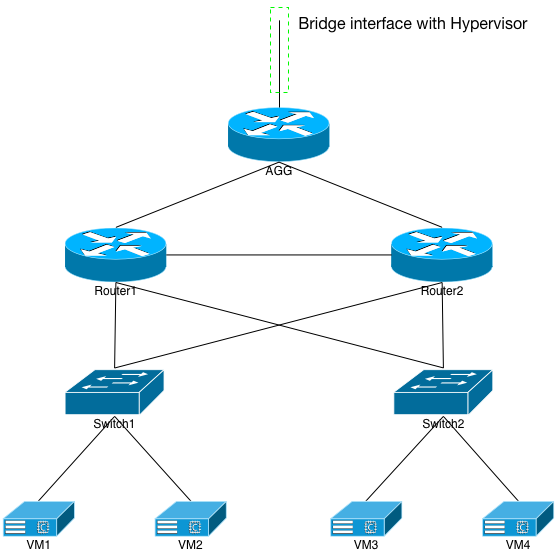
This section is going to get somewhat verbose with the actual configuration of the VMs’ XML, the scripts I wrote to make VM creation, deletion, etc easier, as well as how to create the virtual point-to-points displayed in the diagram. If you’re not interested in the creation of the playground, feel free to skip to the next major section.
Entry Point Into Playground
The hypervisor needed a way to get IP traffic into and out of the playground. This wasn’t entirely necessary, as I could have configured everything via each VM’s terminal and just left the whole playground cut off from the network. But I wanted to be able to traceroute into and out of the playground for demonstration purposes, as well as be able to ssh into the VMs once they were up.
To solve that, I created a bridge interface unimaginatively called br0. In the file /etc/sysconfig/network-scripts/ifcfg-br0:
DEVICE=br0
TYPE=Bridge
BOOTPROTO=static
IPADDR=172.16.0.1
NETMASK=255.255.255.252
ONBOOT=yes
I also knew ahead of time that I was going to assign the entire 172.16/12 CIDR block to the playground, and the IP on the AGG router would be 172.16.0.2. So I added another file named /etc/sysconfig/network-scripts/route-br0:
ADDRESS0=172.16.0.0
NETMASK0=255.240.0.0
GATEWAY0=172.16.0.2
And then:
ifup br0
The results:
harleyquinn# ifconfig br0
br0: flags=4163<UP,BROADCAST,RUNNING,MULTICAST>  mtu 9216
        inet 172.16.0.1  netmask 255.255.255.252  broadcast 172.16.0.3
        inet6 fe80::e45a:77ff:fef3:6cb4  prefixlen 64  scopeid 0x20<link>
        ether fe:00:00:00:00:01  txqueuelen 0  (Ethernet)
        RX packets 3730  bytes 488058 (476.6 KiB)
        RX errors 0  dropped 0  overruns 0  frame 0
        TX packets 6096  bytes 771703 (753.6 KiB)
        TX errors 0  dropped 0 overruns 0  carrier 0  collisions 0

harleyquinn# netstat -nr | grep 172.16
172.16.0.0      0.0.0.0         255.255.255.252 U         0 0          0 br0
172.16.0.0      172.16.0.2      255.240.0.0     UG        0 0          0 br0
I didn’t put a physical Ethernet interface from the hypervisor into that bridge because I didn’t need to. I had no intentions of connecting the playground to the rest of my internal network. I just wanted the hypervisor to have IP access to it.
harleyquinn$ brctl show br0
bridge name	bridge id		STP enabled	interfaces
br0		8000.fe0000000001	no		r1agg-e1-tap
As you can see, the virtual AGG router is already connected to this bridge.
Virtual Point to Point Connections
To simulate the network build as close reality as possible, I decided to use Linux’s bridge and tap interfaces for each of the VMs. As shown in Figure 2, each “NIC” on the VM corresponds to a Linux tap interface. The “cable” between each VM connecting them together is the Linux bridge interface.

harleyquinn$ ifconfig r1-e2-tap
r1-e2-tap: flags=4163<UP,BROADCAST,RUNNING,MULTICAST>  mtu 9216
        inet6 fe80::fc00:ff:fe00:12  prefixlen 64  scopeid 0x20<link>
        ether fe:00:00:00:00:12  txqueuelen 500  (Ethernet)
        RX packets 252891  bytes 18018193 (17.1 MiB)
        RX errors 0  dropped 3625  overruns 0  frame 0
        TX packets 30312  bytes 1883708 (1.7 MiB)
        TX errors 0  dropped 0 overruns 0  carrier 0  collisions 0

harleyquinn$ ifconfig r2-e2-tap
r2-e2-tap: flags=4163<UP,BROADCAST,RUNNING,MULTICAST>  mtu 9216
        inet6 fe80::fc00:ff:fe00:22  prefixlen 64  scopeid 0x20<link>
        ether fe:00:00:00:00:22  txqueuelen 500  (Ethernet)
        RX packets 33936  bytes 2980476 (2.8 MiB)
        RX errors 0  dropped 3625  overruns 0  frame 0
        TX packets 249243  bytes 14050419 (13.3 MiB)
        TX errors 0  dropped 0 overruns 0  carrier 0  collisions 0

harleyquinn$ ifconfig r1-r2-br0
r1-r2-br0: flags=4163<UP,BROADCAST,RUNNING,MULTICAST>  mtu 9216
        inet6 fe80::20cc:eff:fecf:2f5e  prefixlen 64  scopeid 0x20<link>
        ether fe:00:00:00:00:12  txqueuelen 0  (Ethernet)
        RX packets 271652  bytes 14225586 (13.5 MiB)
        RX errors 0  dropped 0  overruns 0  frame 0
        TX packets 8  bytes 648 (648.0 B)
        TX errors 0  dropped 0 overruns 0  carrier 0  collisions 0

harleyquinn$ brctl show r1-r2-br0
bridge name	bridge id		STP enabled	interfaces
r1-r2-br0		8000.fe0000000012	no		r1-e2-tap
							r2-e2-tap
As you can see, two tap interfaces (r1-e2-tap and r2-e2-tap) are attached to the bridge interface (r1-r2-br0). I’ve also set them to a higher MTU, which I’ll explain much later. Now if we look into the XML definitions for Router1 and Router2, we can see how these interfaces are used. For Router1:
    <interface type='bridge'>
      <mac address='10:00:00:00:00:12'/>
      <source bridge='r1-r2-br0'/>
      <target dev='r1-e2-tap'/>
      <model type='e1000'/>
      <alias name='net2'/>
      <address type='pci' domain='0x0000' bus='0x00' slot='0x15' function='0x0'/>
    </interface>
And Router2:
    <interface type='bridge'>
      <mac address='10:00:00:00:00:22'/>
      <source bridge='r1-r2-br0'/>
      <target dev='r2-e2-tap'/>
      <model type='e1000'/>
      <alias name='net2'/>
      <address type='pci' domain='0x0000' bus='0x00' slot='0x15' function='0x0'/>
    </interface>
In both cases, note how they use the same source bridge=’r1-r2-br0′, but each has its own target dev, which is the tap interface previously discussed. Once the VMs are started, KVM will automatically add any of the defined taps into their respective bridges for you. But you have to create both sets of interfaces prior to that startup. To make that chore(!) a little easier, I whipped up a script called mk-vm-ints, which you can see in the Appendix later in this document.
Fake Bridge for Management Interfaces
The Arista image that I’ll be using in this exercise grabs the very first defined network interface and assigns it to the VM’s Management 1 interface. There’s no way to prevent that from happening, but I had no intentions of using the mgmt1 interface for anything at all. Knowing this ahead of time, I created another bridge on the hypervisor called fake-br0. In /etc/sysconfig/network-scripts/ifcfg-fake-br0:
DEVICE=fake-br0
TYPE=Bridge
BOOTPROTO=none
ONBOOT=yes
And with:
ifup fake-br0
I had my fake bridge up. No IP access or anything like that. It was needed for a bunch of unused taps to be added by KVM.
harleyquinn# ifconfig fake-br0
fake-br0: flags=4163<UP,BROADCAST,RUNNING,MULTICAST>  mtu 9216
        inet6 fe80::bc1a:3dff:fe26:cb07  prefixlen 64  scopeid 0x20<link>
        ether fe:00:00:00:00:00  txqueuelen 0  (Ethernet)
        RX packets 0  bytes 0 (0.0 B)
        RX errors 0  dropped 0  overruns 0  frame 0
        TX packets 5  bytes 418 (418.0 B)
        TX errors 0  dropped 0 overruns 0  carrier 0  collisions 0
DHCP Server on the Hypervisor
The 4 FreeBSD VMs that come up will need IP addresses assigned to them. Instead of doing that statically, I decided to use DHCP. It would mean that I’d need to have network continuity from the VM to the bridge interface on the hypervisor. In other words: a good test to verify I’d built the network properly. In /etc/dhcp/dhcpd.conf:
subnet 172.16.0.0 netmask 255.255.255.252 {}

subnet 172.31.100.0 netmask 255.255.255.0 {
	option subnet-mask 255.255.255.0;
	option broadcast-address 172.31.100.255;
	option routers 172.31.100.1;
}

host vm1 {
	hardware ethernet 02:00:00:00:01:10;
	fixed-address 172.31.100.10;
}

host vm3 {
	hardware ethernet 02:00:00:00:01:30;
	fixed-address 172.31.100.11;
}

subnet 172.31.200.0 netmask 255.255.255.0 {
	option subnet-mask 255.255.255.0;
	option broadcast-address 172.31.200.255;
	option routers 172.31.200.1;
}

host vm2 {
	hardware ethernet 02:00:00:00:01:20;
	fixed-address 172.31.200.10;
}

host vm4 {
	hardware ethernet 02:00:00:00:01:40;
	fixed-address 172.31.200.11;
}
And then from harleyquinn’s CLI:
systemctl enable dhcpd
systemctl start dhcpd
Building an Arista vEOS VM
At this point the hypervisor was ready from a configuration perspective. Let’s build an Arista VM, shall we? We’ll need two images from Arista’s download page. Note that you’ll need to set up an account with Arista to download their virtual “lab” images. Near the bottom of the list on the download page, expand the “vEOS” entry. The first image you’ll need is: Aboot-veos-2.0.8.iso. It’s the ISO that every Arista VM you create will need to reference. The next is the actual disk image where EOS lives. As of this writing: vEOS-lab-4.15.2.1F.vmdk.
I decided to put all of the disk images for KVM in the /home/qemu directory. I also made a /home/qemu/.readonly directory for storage of the read-only image files. With that, I had to prep the files for use. The ISO file was ready to go as is, I just renamed it. The VMDK file is a VMWare ESX image, and needs to be converted into something that KVM can understand.
mv Aboot-veos-2.0.8.iso /home/qemu/.readonly/veos-boot.iso
qemu-img convert -O qcow2 vEOS-lab-4.15.2.1F.vmdk /home/qemu/.readonly/veos.img
chmod -R a-w /home/qemu/.readonly
The ISO file will be left as is and just read in by KVM each time an Arista VM is spun up. Each VM will need its own writeable IMG file though:
cd /home/qemu
cp .readonly/veos.img ./agg.img
cp .readonly/veos.img ./router1.img
cp .readonly/veos.img ./router2.img
cp .readonly/veos.img ./switch1.img
cp .readonly/veos.img ./switch2.img
chmod u+w *.img
I won’t put a lot of the VM XML in this section as I’ve provided them all in Appendix A. Look through the entry for the agg router to understand how a vEOS image needs to be configured to boot. That ISO image must always be referenced, so it is a bit slow to start. You can also see how the very first interface (mgmt1 on the router) defined in the XML is attached to the previously created fake-br0 interface. In the case of the agg router, the second interface (eth1 on the router) is bridged in with the br0 interface that I created. This is the only VM I’ll attach to that bridge because I want the agg router to be ingress and egress point of the network. The rest of the interfaces are defined as point-to-points with other VMs.
If you want to copy my XML file as is from the appendix, feel free. That’s why it’s there. Once you have it saved on disk, load it into KVM and then use the scripts I wrote to create the bridge and tap interfaces, and then start the VM:
virsh define agg.xml
mk-vm-ints agg
start-vm agg
Once these commands have been executed, attach to the new VM’s console and waaaaaiiiit a while:
virsh console agg
You’ll eventually be presented with a login prompt. The default user is ‘admin’ with no password to start. Change that quickly. Instead of cluttering this section with router and switch configuration lines, refer to Appendix C, in this case the agg router‘s config. Pay attention to three interfaces specifically: Management1, Eth1, and Loopback0. Note that Management1 is shut down, Eth1 has the 172.16.0.2/30 IP address that I’ll use as the entry point into the network, and Loopback0 is addressed 172.16.0.10/32. The router’s default route is also statically set to point to the Linux bridge’s 172.16.0.1. Assuming everything is configured properly, I should be able to ping the router’s Loopback0 interface from harleyquinn:
harleyquinn# ping 172.16.0.10
PING 172.16.0.10 (172.16.0.10) 56(84) bytes of data.
64 bytes from 172.16.0.10: icmp_seq=1 ttl=64 time=9.13 ms
64 bytes from 172.16.0.10: icmp_seq=2 ttl=64 time=9.48 ms
64 bytes from 172.16.0.10: icmp_seq=3 ttl=64 time=9.29 ms
64 bytes from 172.16.0.10: icmp_seq=4 ttl=64 time=9.01 ms
64 bytes from 172.16.0.10: icmp_seq=5 ttl=64 time=7.38 ms
64 bytes from 172.16.0.10: icmp_seq=6 ttl=64 time=9.51 ms
^C
--- 172.16.0.10 ping statistics ---
6 packets transmitted, 6 received, 0% packet loss, time 5007ms
rtt min/avg/max/mdev = 7.387/8.970/9.519/0.738 ms
The next step was to create router1 and router2, as I did with the agg router. Again, their XML files are included in the appendix below, so feel free to snag them and save them locally. Once spun up (after the waiting for the first boot…) I configured their uplinks to line up with the agg router’s Eth2 and Eth3 interfaces. I then configured a very simple EBGP peer between the agg and each of the two routers. Again, please reference their respective configs in the appropriate section of the appendix.
Assuming that was all done properly, the agg router should have BGP knowledge of the two routers’ Loopback0 interfaces:
agg#show ip route 172.16.0.11

VRF name: default
Codes: C - connected, S - static, K - kernel,
       O - OSPF, IA - OSPF inter area, E1 - OSPF external type 1,
       E2 - OSPF external type 2, N1 - OSPF NSSA external type 1,
       N2 - OSPF NSSA external type2, B I - iBGP, B E - eBGP,
       R - RIP, I L1 - ISIS level 1, I L2 - ISIS level 2,
       A B - BGP Aggregate, A O - OSPF Summary,
       NG - Nexthop Group Static Route

 B E    172.16.0.11/32 [200/0] via 172.17.0.1, Ethernet2

agg#show ip route 172.16.0.12

VRF name: default
Codes: C - connected, S - static, K - kernel,
       O - OSPF, IA - OSPF inter area, E1 - OSPF external type 1,
       E2 - OSPF external type 2, N1 - OSPF NSSA external type 1,
       N2 - OSPF NSSA external type2, B I - iBGP, B E - eBGP,
       R - RIP, I L1 - ISIS level 1, I L2 - ISIS level 2,
       A B - BGP Aggregate, A O - OSPF Summary,
       NG - Nexthop Group Static Route

 B E    172.16.0.12/32 [200/0] via 172.17.0.3, Ethernet3
And harleyquinn should be able to ping them both:
harleyquinn# ping 172.16.0.11
PING 172.16.0.11 (172.16.0.11) 56(84) bytes of data.
64 bytes from 172.16.0.11: icmp_seq=1 ttl=63 time=30.1 ms
64 bytes from 172.16.0.11: icmp_seq=2 ttl=63 time=34.6 ms
64 bytes from 172.16.0.11: icmp_seq=3 ttl=63 time=33.6 ms
64 bytes from 172.16.0.11: icmp_seq=4 ttl=63 time=30.9 ms
64 bytes from 172.16.0.11: icmp_seq=5 ttl=63 time=29.5 ms
64 bytes from 172.16.0.11: icmp_seq=6 ttl=63 time=29.7 ms
^C
--- 172.16.0.11 ping statistics ---
6 packets transmitted, 6 received, 0% packet loss, time 5006ms
rtt min/avg/max/mdev = 29.549/31.459/34.697/2.002 ms
harleyquinn# ping 172.16.0.12
PING 172.16.0.12 (172.16.0.12) 56(84) bytes of data.
64 bytes from 172.16.0.12: icmp_seq=1 ttl=63 time=37.2 ms
64 bytes from 172.16.0.12: icmp_seq=2 ttl=63 time=26.3 ms
64 bytes from 172.16.0.12: icmp_seq=3 ttl=63 time=24.4 ms
64 bytes from 172.16.0.12: icmp_seq=4 ttl=63 time=32.6 ms
64 bytes from 172.16.0.12: icmp_seq=5 ttl=63 time=25.1 ms
^C
--- 172.16.0.12 ping statistics ---
5 packets transmitted, 5 received, 0% packet loss, time 4006ms
rtt min/avg/max/mdev = 24.439/29.163/37.245/4.976 ms
A Note on Performance
It’s important to note that these Arista VMs are meant purely for configuration verification and testing. They’re not meant for performance testing. They will and should never be used in a production environment, nor as a replacement for something like OpenVSwitch on a hypervisor. Every packet in and out of them is CPU switched, and incredibly slow at that. Note the ~30ms ping times between the VMs and the hypervisor. That’s perfectly expected with this type of software. The ping times will get a lot worse as I build more and more of the network. It doesn’t imply a problem, just that, again: these images are not meant for performance testing.
FreeBSD VMs
After finishing the above steps, and also performing the same for switch1 and switch2, it’s time to create 4 FreeBSD VMs that will act as our servers. As mentioned previously, I grabbed the pre-made FreeBSD 10.2 VM QCOW2 image from FreeBSD.org and saved it as a file called /home/qemu/.readonly/freebsd.img. Then from the hypervisor:
cd /home/qemu
cp .readonly/freebsd.img ./vm1.img
cp .readonly/freebsd.img ./vm2.img
cp .readonly/freebsd.img ./vm3.img
cp .readonly/freebsd.img ./vm4.img
chmod u+w vm*.img
The XML configurations for each of the VMs is included in the appendix; again, take what you like. Install them into KVM, make the interfaces, and start them using the scripts I provided. They will come up stupid with no serial console configured, nor any networking. You’ll have to use your favorite VNC client to connect to each one, log in as root, and add this to /boot/loader.conf:
console="comconsole"
Reboot the VMs and you’ll be able to virsh console to them once they begin booting.
They don’t have an /etc/rc.conf on them, so we’ll add one:
hostname="vm1.localdomain.com"
ifconfig_em0="up"
ifconfig_em0="DHCP"
sshd_enable="YES"
sendmail_enable="YES"
But remember: we don’t have a contiguous path between the VMs and the hypervisor. So they’ll never get a DHCP response. We’ll fix that in the next section.
Network Build: L2 VLANs Spanned

Our first network build will look like Figure 3, and will span VLANs 100 and 200 between router1, router2, switch1, and switch2. VLAN 999 will also be spanned between the two routers so that routing protocols can work. You can see from the colored lines in the diagram that VMs 1 and 3 should end up on VLAN 100, while VMs 2 and 4 end up on VLAN 200.
Prevent Logical Loops: Spanning Tree
Before we go trunking VLANs between the devices, we’ll want to make sure our loop prevention technology is configured the way we expect. Arista switches come up with MSTP configured by default, which will work well enough to prevent the network from going offline. We’ll want to set router1 as the STP root, with router2 a slightly higher priority. We’ll then set the switches at the highest priority (higher priority number means less attractive in STP) possible so that they never try to take over as the root.
Check the configs below, and you’ll see that router1 as a priority of 4096 which is the lowest it can go. Router2 has a priority of 16384, while the two switches have their priorities set to 61440.
With these in place, the VLAN trunking we’re about to do will happen without causing any logical loops. I’ll touch more upon STP a bit later in this section.
Trunk Ports
Reference the router and switch configurations in the appropriate section of the appendix. In them, you’ll note that the router downlinks to the switches have VLANs 100 and 200 trunked, and the switches’ uplink ports have the same. Further, the routers’ Eth2 is also trunking across VLAN 999. To make all of this work properly, VLANs 100,200, and 999 will need to be defined on the 2 routers; VLANs 100 and 200 will be defined on the switches.
Access Ports
Each switch should have 2 access ports: Eth3 and Eth4. Eth3 will be an access port for VLAN 100, while Eth4 is for VLAN 200. Pretty simple stuff.
VLAN Interfaces
In our first build, the routers will be providing all of the L2/L3 conversions and routing. Therefore they’ll need VLAN Interfaces for 100, 200, and 999. I created the VLAN999 interfaces on the routers first, and set their IPs to a simple /31 broadcast domain. With the appropriate OSPF and BGP configurations added (see the configs below), I instantly had OSPF and iBGP running between the two routers:
router1#show ip ospf ne
Neighbor ID     VRF      Pri State                  Dead Time   Address         Interface
172.16.0.12     default  1   FULL/BDR               00:00:31    172.18.0.1      Vlan999
router1#show ip bgp summary
BGP summary information for VRF default
Router identifier 172.16.0.11, local AS number 65200
Neighbor Status Codes: m - Under maintenance
  Neighbor         V  AS           MsgRcvd   MsgSent  InQ OutQ  Up/Down State  PfxRcd PfxAcc
  172.16.0.12      4  65200           3128      3110    0    0    2d01h Estab  6      5
  172.17.0.0       4  65100           3045      3245    0    0 03:27:29 Estab  1      1
Again, reference the configs below: Since the routers will be providing an HA routed path for the VLANs, we’ll configure VRRP on interfaces VLAN100 and VLAN200. Each router will be either .2 or .3 respectively, and the VRRP address will be .1, which is the default route of the VLANs.
Once these are configured, you should be able to see VRRP sync up between the two routers:
router1#show vrrp brief
Interface Vrf        Id  Ver Pri Time  State   VrIps
Vlan100   default    1   2   105 3589  Master  172.31.100.1
Vlan200   default    1   2   105 3589  Master  172.31.200.1
router2#show vrrp br
Interface Vrf        Id  Ver Pri Time  State   VrIps
Vlan100   default    1   2   100 3609  Backup  172.31.100.1
Vlan200   default    1   2   100 3609  Backup  172.31.200.1
I went ahead and configured VLAN100 and VLAN200 interfaces on both switches as well, addressing them .3 and .4 respectively in each VLAN. I also set their default routes to point to the VLAN100 VRRP address of 172.31.100.1. With that, I was able to ping them from the hypervisor:
harleyquinn# ping 172.31.100.4
PING 172.31.100.4 (172.31.100.4) 56(84) bytes of data.
64 bytes from 172.31.100.4: icmp_seq=1 ttl=62 time=111 ms
64 bytes from 172.31.100.4: icmp_seq=2 ttl=62 time=115 ms
64 bytes from 172.31.100.4: icmp_seq=3 ttl=62 time=104 ms
64 bytes from 172.31.100.4: icmp_seq=4 ttl=62 time=110 ms
^C
--- 172.31.100.4 ping statistics ---
5 packets transmitted, 4 received, 20% packet loss, time 4005ms
rtt min/avg/max/mdev = 104.059/110.442/115.464/4.116 ms
That step isn’t necessary, but I included it in the write-up anyway.
One last bit needs to be added to the routers’ VLAN interfaces. Since the VMs we’ve created as broadcasting out DHCP requests and our hypervisor is ready to answer, we need to provide a DHCP IP helper address on VLANs 100 and 200. So we’ll add this to both VLAN interfaces on both routers:
ip helper-address 172.16.0.1
And within a short amount of time, we should be able to ping our VMs from the hypervisor:
harleyquinn# ping 172.31.100.10
PING 172.31.100.10 (172.31.100.10) 56(84) bytes of data.
64 bytes from 172.31.100.10: icmp_seq=1 ttl=62 time=88.1 ms
64 bytes from 172.31.100.10: icmp_seq=2 ttl=62 time=97.1 ms
64 bytes from 172.31.100.10: icmp_seq=3 ttl=62 time=91.3 ms
64 bytes from 172.31.100.10: icmp_seq=4 ttl=62 time=96.6 ms
64 bytes from 172.31.100.10: icmp_seq=5 ttl=62 time=87.8 ms
64 bytes from 172.31.100.10: icmp_seq=6 ttl=62 time=88.8 ms
^C
--- 172.31.100.10 ping statistics ---
6 packets transmitted, 6 received, 0% packet loss, time 5007ms
rtt min/avg/max/mdev = 87.823/91.646/97.103/3.878 ms
It Works, Doesn’t It?
If you’ve followed my previous entries, you’ll note that I don’t approve of this style of network building. “Why?” you might ask, “Doesn’t it work?” Assuming everything is configured and working properly, then our little network will function. STP is the key to it working, though. We’ve configured router1 as the root, so if we peek at its STP status for one of the VLANs:
router1#show spanning-tree vlan 100
Spanning tree instance for vlan 100
MST0
  Spanning tree enabled protocol mstp
  Root ID    Priority    4096
             Address     0200.00e5.2918
             This bridge is the root

  Bridge ID  Priority     4096  (priority 4096 sys-id-ext 0)
             Address     0200.00e5.2918
             Hello Time  2.000 sec  Max Age 20 sec  Forward Delay 15 sec

Interface        Role       State      Cost      Prio.Nbr Type
---------------- ---------- ---------- --------- -------- --------------------
Et2              designated forwarding 2000      128.2    P2p
Et3              designated forwarding 2000      128.3    P2p
Et4              designated forwarding 2000      128.4    P2p
We see that router2 is working similarly, though it notes where the root is:
router2#show spanning-tree vlan 100
Spanning tree instance for vlan 100
MST0
  Spanning tree enabled protocol mstp
  Root ID    Priority    4096
             Address     0200.00e5.2918
             Cost        0 (Ext) 2000 (Int)
             Port        2 (Ethernet2)
             Hello Time  2.000 sec  Max Age 20 sec  Forward Delay 15 sec

  Bridge ID  Priority    16384  (priority 16384 sys-id-ext 0)
             Address     0200.0095.c4ca
             Hello Time  2.000 sec  Max Age 20 sec  Forward Delay 15 sec

Interface        Role       State      Cost      Prio.Nbr Type
---------------- ---------- ---------- --------- -------- --------------------
Et2              root       forwarding 2000      128.2    P2p
Et3              designated forwarding 2000      128.3    P2p
Et4              designated forwarding 2000      128.4    P2p
Finally, each of the switches have one of their ports in discard mode. This is how the logical loop is prevented:
switch1#show spanning-tree vlan 100
Spanning tree instance for vlan 100
MST0
  Spanning tree enabled protocol mstp
  Root ID    Priority    4096
             Address     0200.00e5.2918
             Cost        0 (Ext) 2000 (Int)
             Port        1 (Ethernet1)
             Hello Time  2.000 sec  Max Age 20 sec  Forward Delay 15 sec

  Bridge ID  Priority    61440  (priority 61440 sys-id-ext 0)
             Address     0200.0008.df87
             Hello Time  2.000 sec  Max Age 20 sec  Forward Delay 15 sec

Interface        Role       State      Cost      Prio.Nbr Type
---------------- ---------- ---------- --------- -------- --------------------
Et1              root       forwarding 2000      128.1    P2p
Et2              alternate  discarding 2000      128.2    P2p
Et3              designated forwarding 2000      128.3    P2p Edge
So what’s the problem, other than an inefficient use of the switches’ uplinks? Well, let’s assume someone misconfigures STP on router2. Or worse, the router just breaks for some reason, disabling all of its STP safeguards (I’ve seen things like this happen with other routers). We can simulate that by just removing the STP configuration from router2, and then trying to ping something that isn’t already ARP cached. Bad things are about to happen…
router2#conf t
router2(config)#no spanning-tree mst 0 priority 16384
router2(config)#spanning-tree mode none
router2(config)#
With this, we no longer have router2 participating in STP. Hm. Trouble already?
harleyquinn# uptime
 13:48:12 up 2 days,  2:24,  2 users,  load average: 1.61, 0.78, 0.60
The switches both see router2 no longer participating, which means their uplink to router2 becomes a valid path:
switch1#show spanning-tree vlan 100
Spanning tree instance for vlan 100
MST0
  Spanning tree enabled protocol mstp
  Root ID    Priority    4096
             Address     0200.00e5.2918
             Cost        0 (Ext) 2000 (Int)
             Port        1 (Ethernet1)
             Hello Time  2.000 sec  Max Age 20 sec  Forward Delay 15 sec

  Bridge ID  Priority    61440  (priority 61440 sys-id-ext 0)
             Address     0200.0008.df87
             Hello Time  2.000 sec  Max Age 20 sec  Forward Delay 15 sec

Interface        Role       State      Cost      Prio.Nbr Type
---------------- ---------- ---------- --------- -------- --------------------
Et1              root       forwarding 2000      128.1    P2p
Et2              designated forwarding 2000      128.2    P2p
Et3              designated forwarding 2000      128.3    P2p Edge
Let’s do something silly like ping one of the VMs from router2:
router2#ping 172.31.200.10
PING 172.31.200.10 (172.31.200.10) 72(100) bytes of data.
From 172.31.200.3 icmp_seq=1 Destination Host Unreachable
From 172.31.200.3 icmp_seq=2 Destination Host Unreachable
From 172.31.200.3 icmp_seq=3 Destination Host Unreachable
^C
--- 172.31.200.10 ping statistics ---
5 packets transmitted, 0 received, +3 errors, 100% packet loss, time 4002ms
Well that didn’t work. What about pinging the uplink IP on the agg router from router2?
router2#ping 172.17.0.2
PING 172.17.0.2 (172.17.0.2) 72(100) bytes of data.
^C
--- 172.17.0.2 ping statistics ---
5 packets transmitted, 0 received, 100% packet loss, time 4003ms
Nothing. How’s the hypervisor doing?
harleyquinn# uptime
 13:50:34 up 2 days,  2:27,  2 users,  load average: 3.90, 2.04, 1.10
Not good. The load average is still ticking upward. And everything below the agg router is gone from the hypervisor’s perspective:
harleyquinn# ping 172.16.0.10
PING 172.16.0.10 (172.16.0.10) 56(84) bytes of data.
64 bytes from 172.16.0.10: icmp_seq=1 ttl=64 time=11.9 ms
64 bytes from 172.16.0.10: icmp_seq=2 ttl=64 time=12.1 ms
64 bytes from 172.16.0.10: icmp_seq=3 ttl=64 time=11.3 ms
^C
--- 172.16.0.10 ping statistics ---
3 packets transmitted, 3 received, 0% packet loss, time 2003ms
rtt min/avg/max/mdev = 11.381/11.800/12.102/0.330 ms
harleyquinn# ping 172.16.0.11
PING 172.16.0.11 (172.16.0.11) 56(84) bytes of data.
From 172.16.0.2: icmp_seq=1 Redirect Host(New nexthop: 172.16.0.1)
From 172.16.0.2 icmp_seq=1 Redirect HostFrom 172.16.0.2: icmp_seq=2 Redirect Host(New nexthop: 172.16.0.1)
From 172.16.0.2 icmp_seq=2 Redirect HostFrom 172.16.0.2: icmp_seq=3 Redirect Host(New nexthop: 172.16.0.1)
From 172.16.0.2 icmp_seq=3 Redirect Host^C
--- 172.16.0.11 ping statistics ---
3 packets transmitted, 0 received, +3 errors, 100% packet loss, time 2002ms
Let’s fix this by re-enabling STP on router2:
router2#conf t
router2(config)#spanning-tree mode mstp
router2(config)#spanning-tree mst 0 priority 16384
router2(config)#end
Fortunately, doing this in a hypervisor provides two benefits. First: everything is self-contained on the hypervisor and it doesn’t affect any other physical network device. Second: the way the serial console is virtualized for the VMs doesn’t get affected by the management plane of the VM becoming unresponsive. In a real scenario, the serial consoles on each of the devices would have become unresponsive because the management processors would be running at 100%, dealing with the broadcast storm(s). And it’s for this very reason that I call this network build: amateur hour. Don’t. Do. It. Let’s learn a different way to do it.
Network Build: L3 and VXLAN
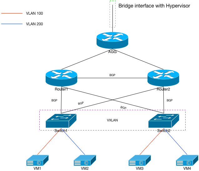
If we examine the diagram in Figure 4, we see an architecture that looks very similar to the previous one. However, close examination of the point-to-point connections between routers and switches reveals a routing protocol (BGP) running as opposed to L2 VLANs being trunked. The routers and switches will need to be reconfigured quite a bit to make this happen; their config bits are summarized in configuration section of the appendix.
As displayed, this architecture will put both switch1 and switch2 into their own, individual failure domains. The same applies for router1 and router2. Each is independent of the other, only tied together via routing protocols. If one of the devices fails, it will have little to no affect on the other devices.
From a reliability perspective, this is far more desirable than the previous spanned VLAN configuration. However, if you still need VLANs 100 and 200 shared between the 2 switches, this configuration will partition them. This section will explain how to use VXLAN to join the partitions together, but not compromise the underlying network.
The Routers
Look through the configuration of the two routers, and you’ll see that they no longer have L2 knowledge of VLANs 100 and 200. In fact, they don’t have any switchports configured on them any longer. Every port has an IP address and a routing protocol running across it. As I discussed in my previous VXLAN article, I prefer to use EBGP between the routers and switches. The routers have a similar set of prefix lists on them as the upstream agg router does: Default and NoDefault. They send only default down to the switches and accept anything from the switches except default. Further, they’re set up to accept the same prefixes from multiple (up to 16) sources; they’ll ECMP across each of them.
The Switches
The uplinks on the switches are no longer switchports; instead of they have IPs corresponding to the appropriate interfaces on the upstream routers. Their BGP configurations are identical in that they’re in the same ASN and are accepting the same prefixes from up to 16 sources for ECMP. They also have loopback0 interfaces, and are redistributing their connected interfaces into BGP.
Since we still VLANs 100 and 200 defined and routed somewhere, we’ll do that on each of the switches now instead of the routers. Each switch gets a VLAN interface for 100 and 200, and an appropriate IP address set on it. Further, the ip helper address for DHCP requests needs to be configured on those VLAN interfaces.
Once this is completed and the switches are redistributing their connected into BGP, the upstream routers will begin to see two forwarding entries for each of the VLANs:
router1#show ip route 172.31.100.0

VRF name: default
Codes: C - connected, S - static, K - kernel,
       O - OSPF, IA - OSPF inter area, E1 - OSPF external type 1,
       E2 - OSPF external type 2, N1 - OSPF NSSA external type 1,
       N2 - OSPF NSSA external type2, B I - iBGP, B E - eBGP,
       R - RIP, I L1 - ISIS level 1, I L2 - ISIS level 2,
       A B - BGP Aggregate, A O - OSPF Summary,
       NG - Nexthop Group Static Route

 B E    172.31.100.0/24 [200/0] via 172.18.1.1, Ethernet3
                                via 172.18.1.3, Ethernet4
But with this set up, we’ve partitioned VLANs 100 and 200. 50% of the flows from router1 will hit switch1 and the other 50% will hit switch2. If the destination is on switch1, that will work fine. Otherwise, the packet will get black-holed.
VXLAN Between the Switches
To provide a contiguous VLAN100 and 200, we’ll need to configure VXLAN between the two switches. Fortunately on an Arista, this is very simple to do. Note that I haven’t configured VXLAN on another network device (as of yet), but I imagine it’s just as simple. We have to prepare the switches and VLAN interfaces to participate first, before we connect the two of them together with the overlay. First and foremost is the:
ip virtual-router mac-address 02:37:b3:1a:d6:5d
The MAC addressed entered here can be anything. But it HAS to be the same MAC addressed used on every participating device in the entire VXLAN mesh. I’ll explain why in a moment.
Second, things like HSRP and/or VRRP won’t work properly across VXLAN. Instead, we have to add this to each of the VLAN interfaces:
interface Vlan100
   ip virtual-router address 172.31.100.1
!
interface Vlan200
   ip virtual-router address 172.31.200.1
This will allow each VLAN interface to provide the same XX.YY.ZZ.1 default route for their respective servers. The aforementioned MAC address is used with each of the ip virtual-router addresses, and each switch participating in the VXLAN domain needs to agree on that MAC so that they ignore it from other switches. They should see ARP responses coming in from other devices for, for instance, 172.31.100.1 with the same MAC address they have configured locally, and just ignore that packet. If the switches had differing MAC addresses set, the servers using .1 would become confused because they’d see all of the ARP responses from each of the switches and not know which to use. So make sure that ip virtual-router MAC is the same across the infrastructure!
With that done, we’ll create a new interface called VXLAN1, where we define things like the VNI to VLAN mapping as well as any of the other participating devices. The loopbacks for switch1 and switch2 are 172.16.0.13 and .14 respectively. The VXLAN interface on switch1 would look like:
interface Vxlan1
   vxlan source-interface Loopback0
   vxlan udp-port 4789
   vxlan vlan 100 vni 100
   vxlan vlan 200 vni 200
   vxlan flood vtep 172.16.0.14
Obviously, switch2’s VXLAN interface would be identical except for the last line, instead referencing switch1’s loopback. What this does is tell each switch that the other switch is also a VTEP, or tunnel endpoint for VXLAN. With this in place, we now have VXLAN running between the two devices, and we’ve provided a direct 1-to-1 mapping of the VLANs (100, 200) to their own VNIs.
How do we know this? Well from switch1, we can try to ping vm3, which we know is physically connected to switch2 but in VLAN100:
switch1#show ip route 172.31.100.11

VRF name: default
Codes: C - connected, S - static, K - kernel,
       O - OSPF, IA - OSPF inter area, E1 - OSPF external type 1,
       E2 - OSPF external type 2, N1 - OSPF NSSA external type 1,
       N2 - OSPF NSSA external type2, B I - iBGP, B E - eBGP,
       R - RIP, I L1 - ISIS level 1, I L2 - ISIS level 2,
       A B - BGP Aggregate, A O - OSPF Summary,
       NG - Nexthop Group Static Route

 C      172.31.100.0/24 is directly connected, Vlan100

switch1#ping 172.31.100.11
PING 172.31.100.11 (172.31.100.11) 72(100) bytes of data.
80 bytes from 172.31.100.11: icmp_req=1 ttl=64 time=187 ms
80 bytes from 172.31.100.11: icmp_req=2 ttl=64 time=74.8 ms
80 bytes from 172.31.100.11: icmp_req=3 ttl=64 time=73.3 ms
80 bytes from 172.31.100.11: icmp_req=4 ttl=64 time=98.3 ms
80 bytes from 172.31.100.11: icmp_req=5 ttl=64 time=96.5 ms

--- 172.31.100.11 ping statistics ---
5 packets transmitted, 5 received, 0% packet loss, time 676ms
rtt min/avg/max/mdev = 73.317/106.079/187.397/41.988 ms, ipg/ewma 169.173/145.952 ms
switch1#show arp 172.31.100.11
Address         Age (min)  Hardware Addr   Interface
172.31.100.11           0  0200.0000.0130  Vlan100, Vxlan1
Switch1 has a directly connected interface (Vlan100), and it can ping vm3 directly. The last line in the show arp command is telling us that switch1 has learned the ARP for vm3 via both Vlan100 and Vxlan1. If we dig into it some more and query the switch about vm3‘s MAC address:
switch1#show mac address-table address 0200.0000.0130
          Mac Address Table
------------------------------------------------------------------

Vlan    Mac Address       Type        Ports      Moves   Last Move
----    -----------       ----        -----      -----   ---------
 100    0200.0000.0130    DYNAMIC     Vx1        1       161 seconds ago
Total Mac Addresses for this criterion: 1
Again: known via Vx1 or Vxlan1. That doesn’t really help us know which switch vm3 is on though, assuming we didn’t already. This example is simple because we know there’s only one other switch participating in VXLAN. But what if it were 10 switches and 2 routers? Fortunately, we can find out which VTEP that MAC address was learned from:
switch1#show vxlan address-table address 0200.0000.0130
          Vxlan Mac Address Table
----------------------------------------------------------------------

Vlan  Mac Address     Type     Prt  Vtep             Moves   Last Move
----  -----------     ----     ---  ----             -----   ---------
 100  0200.0000.0130  DYNAMIC  Vx1  172.16.0.14      1       0:00:02 ago
Total Remote Mac Addresses for this criterion: 1
This output shows us that the MAC for vm3 came from switch2.
Watch Those MTUs
It’s important to remember that VXLAN is an encapsulation technology. That means each switch will need to add a small amount of data to each of the packets it’s processing before it puts the packet back onto the wire. If the pre-processed packets were already at the default size of 1500 bytes, the resulting encapsulated packets will be too big to traverse the links without fragmentation.
To solve that, we’ll set all of the interfaces between the routers and switches to 9000. This is why I made the tap interfaces on the Linux hypervisor 9216 (per my start-vm script).
With that, we have a pair of contiguous VLANs between the two switches without any VLAN spanning, and we can send TCP traffic:
harleyquinn# telnet 172.31.100.11 22
Trying 172.31.100.11...
Connected to 172.31.100.11.
Escape character is '^]'.
SSH-2.0-OpenSSH_6.6.1_hpn13v11 FreeBSD-20140420
quit
Protocol mismatch.
Connection closed by foreign host.
We could stop here and call it a day. The entire overlay is riding on top of a solid L3 infrastructure without any worries or needs of a loop prevention technology such as STP. But, good enough isn’t…
Eliminating Hairpinning Incoming Traffic
If we leave the network configured as described in the previous section, we’ll have to understand that 50% of the incoming flows for any of the VMs will hairpin. Each of the routers will ECMP across the switches that are announcing knowledge of the appropriate VLANs. In our example: that’s both switches. 50% of the traffic destined for vm1, for instance, will go directly to switch1 and to vm1. The other 50% of the flows will to go switch2 first, be encapsulated into a VXLAN tunnel and sent back to switch1 via either router1 or router2.
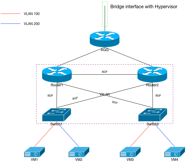
In other words, it’ll hairpin. In fact, the more target switches we add to the VXLAN mesh, the greater the percentage chance of hairpinning incoming traffic.
We can stop the hairpinning by extending VXLAN from the switches up to router1 and router2. If we do that, both of the routers will then have L2 knowledge of each of the VMs on VLANs 100 and 200, and they’ll perform the VXLAN encapsulation at the router before sending the packets directly to the appropriate switch. Hairpinning won’t happen after that.
The changes are pretty simple and I won’t go through each individual device to explain them. If you’ve followed along so far, you’ll pretty much have a good idea of what needs to be done. As a reminder, we’ll need to (re)define VLANs 100 and 200 on the routers, and set up VLAN100 and VLAN200 interfaces on both devices. If you note in the switch configurations, I left IPs .2 and .3 in both /24s available.
The routers will not need a virtual-router MAC address set globally, nor will each of their VLAN interfaces need virtual-router IP addresses set. Those two configuration options are only needed on devices that are providing a default route for the VLANs in question. Since the routers aren’t doing that, they don’t need the MAC or virtual-router IP.
Does it work? Let’s check router2 and ask it about vm2:
router2#show ip route 172.31.200.10

VRF name: default
Codes: C - connected, S - static, K - kernel,
       O - OSPF, IA - OSPF inter area, E1 - OSPF external type 1,
       E2 - OSPF external type 2, N1 - OSPF NSSA external type 1,
       N2 - OSPF NSSA external type2, B I - iBGP, B E - eBGP,
       R - RIP, I L1 - ISIS level 1, I L2 - ISIS level 2,
       A B - BGP Aggregate, A O - OSPF Summary,
       NG - Nexthop Group Static Route

 C      172.31.200.0/24 is directly connected, Vlan200

router2#ping 172.31.200.10
PING 172.31.200.10 (172.31.200.10) 72(100) bytes of data.
80 bytes from 172.31.200.10: icmp_req=1 ttl=64 time=54.5 ms
80 bytes from 172.31.200.10: icmp_req=2 ttl=64 time=64.8 ms
80 bytes from 172.31.200.10: icmp_req=3 ttl=64 time=81.1 ms
80 bytes from 172.31.200.10: icmp_req=4 ttl=64 time=84.0 ms
80 bytes from 172.31.200.10: icmp_req=5 ttl=64 time=87.7 ms

--- 172.31.200.10 ping statistics ---
5 packets transmitted, 5 received, 0% packet loss, time 226ms
rtt min/avg/max/mdev = 54.505/74.479/87.735/12.683 ms, pipe 2, ipg/ewma 56.623/65.317 ms
router2#show arp 172.31.200.10
Address         Age (min)  Hardware Addr   Interface
172.31.200.10           0  0200.0000.0120  Vlan200, Vxlan1
router2#show mac address-table address 0200.0000.0120
          Mac Address Table
------------------------------------------------------------------

Vlan    Mac Address       Type        Ports      Moves   Last Move
----    -----------       ----        -----      -----   ---------
 200    0200.0000.0120    DYNAMIC     Vx1        1       41 seconds ago
Total Mac Addresses for this criterion: 1

          Multicast Mac Address Table
------------------------------------------------------------------

Vlan    Mac Address       Type        Ports
----    -----------       ----        -----
Total Mac Addresses for this criterion: 0
router2#show vxlan address-table address 0200.0000.0120
          Vxlan Mac Address Table
----------------------------------------------------------------------

Vlan  Mac Address     Type     Prt  Vtep             Moves   Last Move
----  -----------     ----     ---  ----             -----   ---------
 200  0200.0000.0120  DYNAMIC  Vx1  172.16.0.13      1       0:00:48 ago
Total Remote Mac Addresses for this criterion: 1
We can see that router2 has a directly connected interface on 172.31.200.0/24, which means it will look for ARP information for vm2. It finds that information VXLAN from the VTEP 172.16.0.3, which we know to be switch1. It will, therefore, send the packets directly to switch1 every time.
Hairpinning has been eliminated.
Thoughts About This Configuration
I’ve made it clear, multiple times, that I’m not a fan of spanning VLANs via any technology. I don’t believe server1 and server2 ever need to be on the same VLAN. They should be able to talk to one another via IP, following their default route if need be. However, sometimes we’re forced to provide services we don’t agree with, and this VXLAN setup lets engineers build virtually spanned VLANs without compromising the underlying network.
The potential drawbacks? Well, at least with Arista devices, the VTEP configuration is a 1-to-1 sort of thing. It’s very manual. Meshing 2 switches together, or even 2 switches and 2 routers together is pretty easy. It’s 4 devices total. But what if we had 2 routers and, say, 120 switches? VXLAN would work fine across all 122 devices, but the configuration would be tedious. It’s for this reason I strongly encourage some sort of automation or other programatic way to add and subtract VTEPs from the mix. Regardless of the vendor of switch or router.
The second challenge is troubleshooting for folks who don’t have a lot of exposure to VXLAN. This technology does add a bit of confusion to the network. One such area are incoming and outgoing traceroutes. If we get on the hypervisor and traceroute to vm1, it’ll only have three hops (including the agg router):
harleyquinn# traceroute 172.31.100.10
traceroute to 172.31.100.10 (172.31.100.10), 30 hops max, 60 byte packets
 1  172.16.0.2 (172.16.0.2)  166.365 ms  167.268 ms  168.247 ms
 2  172.17.0.3 (172.17.0.3)  512.507 ms  513.863 ms  515.186 ms
 3  172.31.100.10 (172.31.100.10)  1043.302 ms  1044.172 ms  1045.018 ms
But if we hop on vm1 and traceroute back to the hypervisor, it’ll have 4 hops:
root@vm1:~ # traceroute 172.16.0.1
traceroute to 172.16.0.1 (172.16.0.1), 64 hops max, 40 byte packets
 1  172.31.100.4 (172.31.100.4)  72.733 ms  25.661 ms  24.111 ms
 2  172.18.2.0 (172.18.2.0)  53.885 ms  83.657 ms  101.536 ms
 3  172.17.0.2 (172.17.0.2)  190.434 ms  235.230 ms  121.119 ms
 4  172.16.0.1 (172.16.0.1)  145.485 ms  168.028 ms  196.855 ms
Why is that? Well it’s because on incoming packets, router1 and router2 are stuffing the packets into VXLAN tunnels and handing them directly to the appropriate switch. The switch then decapsulates those packets and sends them to the VMs. The traffic that’s put inside the tunnel doesn’t show up in a traceroute. It looks like a L2 transaction at that point. However, tracing the other way never actually hits a VXLAN tunnel. The default route for each VM is the local switch, which then follows its own routing table to either router1 or router2. No tunnels needed.
Neither of these are deal breakers in my opinion. They’re just things that engineers have to be aware of.
VXLAN to the Server
Both Linux and FreeBSD support VXLAN in their respective kernels now. Other OSs may as well. What can we use VXLAN for at the server level? It’s not quite as straightforward as it is with network devices, but there are some interesting use cases. For instance, imagine that your network devices haven’t been updated in years and they just don’t support VXLAN. But, you have a load balancer and a bunch of servers that do. This section will focus on using a load balancing device (an a10 vThunder) that isn’t directly connected to, or otherwise have any direct L2 knowledge of the real servers it’s load balancing for. I’ll demonstrate what happens when you have a remote load balancer and how to rectify the one drawback of that architecture using VXLAN.
The Virtual Architecture
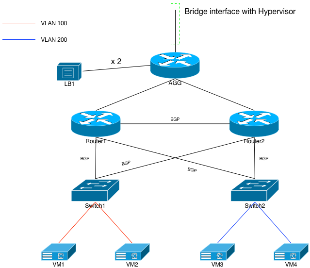
We’re going to stick with the same virtual architecture we’ve been working with all along, but some changes will be made to the switches. Specifically, we’re going to make each switch only responsible for 1 VLAN: 100 on switch1 and 200 on switch2. VXLAN will be removed from the switches and upstream routers. Both VMs on switch1 will be in VLAN100, while both VMs on switch2 in VLAN200.
The VLAN interfaces on both switches will no longer need the virtual-router IP configured; they’ll each have their real IPs set to the .1 of their respective /24.
Once this is done, the upstream routers will only know 172.31.100.0/24 from switch1, and 172.31.200.0/24 from switch2. It’s a very simple build.
Because of this change, we’ll also have to reconfigure the DHCP daemon on harleyquinn. Specifically, we need to move vm2‘s IP into VLAN100 (172.31.100.11/24) and vm3‘s IP into VLAN200 (172.31.200.11/24). VMs 1 and 4 stay as they were.
The Load Balancer
I originally decided to sign up for a10’s virtual Thunder load balancer because I know that their hardware load balancers support VXLAN. The whole idea was to terminate the VTEPs from the servers on to the load balancer. So with that, I grabbed an evaluation copy of their virtual Thunder for KVM.
The image comes as an installation ISO, needs 4G of RAM and at least an 8G disk. I put the ISO in the same /home/qemu/.readonly directory, and used the qemu-img command to create a new disk file in /home/qemu:
qemu-img create -f qcow2 -o preallocation=metadata /home/qemu/lb1.img 8G
The XML for the load balancer‘s VM is included in the appendix. It must first be started by booting from the ISO, but after it runs through the installation, that ISO can be ignored; it will boot directly from the disk image. Another important bit is that, like the Arista VMs, the a10 VM assumes its first interface is an Intel, and that it will be the management interface. So like the routers and switches, I attached that to the same fake-br0 interface on the hypervisor. However, any of the following interfaces must be of type virtio, or the vThunder OS won’t recognize them. As you can see from the XML, I attached those to the agg router’s Eth4 and 5 respectively.
The intent was to use route health injection with an example VIP. This means that I needed a routing protocol running between the agg router and the new lb1. I put lb1 into its own ASN (65400) and EBGP-peered it with the agg router via lb1‘s eth1 interface:
!
interface ethernet 1
  enable
  ip address 172.17.0.5 255.255.255.254
!
!
router bgp 65400
  neighbor 172.17.0.4 remote-as 65100
  neighbor 172.17.0.4 description agg
  neighbor 172.17.0.4 fall-over bfd
  neighbor 172.17.0.4 soft-reconfiguration inbound
  redistribute connected
  redistribute vip only-flagged
And with that, the load balancer had a default route out via the agg router:
lb1#show ip route 0.0.0.0
Routing entry for 0.0.0.0/0
  Known via "bgp", distance 20, metric 0, best
  Last update 09:51:35 ago
  * 172.17.0.4, via ethernet 1
Server Interface
The second interface on lb1 was intended to communicate with the real servers. I was going to set up another /31 point to point with the agg router, and then initially set up a static route for 172.31.100/24 and .200/24 towards that second agg router IP. This would work fine for the first demonstration, and lead me into the second one using VXLAN on the load balancer. However, to verify that this version of a10’s ACOS supported VXLAN, I tried this:
lb1#conf t
lb1(config)#overlay-tunnel vtep 1
ERROR: Overlay tunnels not supported on this platform
lb1(config)#
(Imagine the old Family Feud game show with Richard Dawson saying, “Survey says?….” BZZZZZZT!
This set me back for only a moment, but I figured out another way to accomplish what I wanted. We’ll get to all that VXLAN stuff later in this section, but for now I had to turn Eth5 on the agg router into a switchport, with a trunk for VLAN 300. I then created interface VLAN300 on the agg router with the IP address of 172.31.30.2/24, a ve 300 interface on the load balancer with an IP of 172.31.30.1/24, and static routes for the two previous /24s pointed to 172.31.30.2/24. From lb1‘s perspective:
vlan 300
  tagged ethernet 2
  router-interface ve 300
!
interface ve 300
  ip address 172.31.30.1 255.255.255.0
!
ip route 172.31.100.0 /24 172.31.30.2
!
ip route 172.31.200.0 /24 172.31.30.2

lb1#traceroute 172.31.100.10
traceroute to 172.31.100.10 (172.31.100.10), 30 hops max, 60 byte packets
 1 172.31.30.2 (172.31.30.2) 233.385 ms 241.333 ms 245.281 ms
 2 172.17.0.3 (172.17.0.3) 369.225 ms 377.219 ms 385.246 ms
 3 172.18.2.1 (172.18.2.1) 469.235 ms 477.179 ms 485.213 ms
 4 172.31.100.10 (172.31.100.10) 669.194 ms 673.127 ms 681.120 ms
Setting up a VIP
The whole point behind a load balancer is to balance incoming requests to a service across n servers. In our environment, each of the VMs automatically starts up an easy service to load balance: sendmail. So we’ll set up a port 25 VIP on lb1 and balance between the 4 VMs. I’ll leave the config for the LB in the appendix, but the basic idea is to first define a set of “real” servers, such as:
slb server vm1 172.31.100.10
  port 25 tcp
    health-check-disable
(Note that I would not normally recommend disabling health checking for a production VIP. This is just for experimentation and educational purposes).
After that, a service group needs to be defined:
slb service-group mail tcp
  member vm1 25
  member vm2 25
  member vm3 25
  member vm4 25
!
And finally, the VIP itself:
slb virtual-server mail 172.31.40.1 /32
  redistribution-flagged
  port 25 tcp
    snat-on-vip
    source-nat auto
    service-group mail
You’ll note I’ve set the “redistribution-flagged” bit for this VIP. Recall lb1‘s BGP configuration has the “redistribute vip only-flagged” also set. Those two combined together force the LB to announce via BGP the VIP’s /32 assuming it’s up and healthy:
lb1#show slb virtual-server
Total Number of Virtual Services configured: 1
Virtual Server Name      IP              Current    Total      Request  Response Peak
Service-Group            Service         connection connection packets  packets  connection
----------------------------------------------------------------------------------------
*mail 172.31.40.1     All Up

    port 25  tcp                         0          26         225      210      0
mail                     25/tcp          0          13         116      115      0
Total received conn attempts on this port: 26
And from the agg router’s perspective:
agg#show ip route 172.31.40.1

VRF name: default
Codes: C - connected, S - static, K - kernel,
       O - OSPF, IA - OSPF inter area, E1 - OSPF external type 1,
       E2 - OSPF external type 2, N1 - OSPF NSSA external type 1,
       N2 - OSPF NSSA external type2, B I - iBGP, B E - eBGP,
       R - RIP, I L1 - ISIS level 1, I L2 - ISIS level 2,
       A B - BGP Aggregate, A O - OSPF Summary,
       NG - Nexthop Group Static Route

 B E    172.31.40.1/32 [200/0] via 172.17.0.5, Ethernet4
And sure enough, from harleyquinn, we can telnet to 172.31.40.1 port 25, and get a response from one of the VMs:
harleyquinn$ telnet 172.31.40.1 25
Trying 172.31.40.1...
Connected to 172.31.40.1.
Escape character is '^]'.
220 vm1.localdomain.com ESMTP Sendmail 8.15.2/8.15.2; Thu, 24 Dec 2015 02:56:11 GMT
Client IP Lost: A Use for VXLAN
With the previous connection still open, if I look on vm1 and see what IP is connecting to its port 25, I’ll find it’s not harleyquinn. It’s actually lb1‘s ve300 interface:
root@vm1:~ # netstat -a | grep smtp
tcp4       0      0 172.31.100.10.smtp     172.31.30.1.24133      ESTABLISHED
You can see that IP 172.31.30.1 is the one that established the connection to sendmail. But I performed the telnet from harleyquinn, what gives? The problem is that lb1 doesn’t have L2 knowledge of any of the real servers. If it were on the same VLANs as the reals, it could just re-write the destination IP address of the incoming port 25 connection to, for instance, vm1‘s IP. It would put the packet onto the wire, and from vm1‘s perspective, the source of the connection would be harleyquinn, not lb1.

That can’t work if lb1 and the servers aren’t on the same VLANs. It forces lb1 to follow its routing table, which in our case is a static route aimed at the agg router. When it does that, it sources the packet from its own ve300 interface, and SNATs it towards vm1. When vm1 gets the packet, it looks like it’s coming from lb1, because it is.
Well we just spent the previous section of this document exploring a way to extend VLANs over a L3 infrastructure, didn’t we? As previously described, we can’t use a10’s virtual Thunder image to run VXLAN locally. It’s not supported, much to my chagrin. But we can hack together an alternative that almost accomplishes the same thing. And that’s to use the agg router as the VTEP for the servers, and then trunk the traffic over to lb1.
Please Note: The goal of this section was to imagine that our network gear does not support VXLAN, but here I go using the agg router to do it. Bear with me, and imagine that the VXLAN configurations that I’m doing on the agg router are actually being done on lb1 instead. In any and every case, it makes sense to extend the VTEPs as far towards their destination as possible. In our case, the limit of that is the agg router.
VXLAN on FreeBSD
Before we get to creating the VTEPs on our FreeBSD VMs, we’ll set up our VXLAN interface on the agg router:
interface Vxlan1
   vxlan source-interface Loopback0
   vxlan udp-port 4789
   vxlan vlan 300 vni 300
   vxlan flood vtep 172.31.100.10 172.31.100.11 172.31.200.10 172.31.200.11
I’ve got the VTEPs ready for all 4 VMs. On the VMs, a simple ifconfig line does the trick. For instance, on vm2:
root@vm2:~ # ifconfig vxlan create vxlanid 300 vxlanlocal 172.31.100.11 vxlanremote 172.16.0.10 inet 172.31.30.11/24
vxlan0
root@vm2:~ # ifconfig vxlan0
vxlan0: flags=8843<UP,BROADCAST,RUNNING,SIMPLEX,MULTICAST> metric 0 mtu 1500
	ether 82:a0:d6:d5:40:b0
	inet 172.31.30.11 netmask 0xffffff00 broadcast 172.31.30.255
	inet6 fe80::80a0:d6ff:fed5:40b0%vxlan0 prefixlen 64 scopeid 0x3
	nd6 options=21<PERFORMNUD,AUTO_LINKLOCAL>
	vxlan vni 300 local 172.31.100.11:4789 remote 172.16.0.10:4789
Do we have ARP knowledge of the agg router?
root@vm2:~ # ping 172.31.30.2
PING 172.31.30.2 (172.31.30.2): 56 data bytes
64 bytes from 172.31.30.2: icmp_seq=0 ttl=64 time=170.027 ms
64 bytes from 172.31.30.2: icmp_seq=1 ttl=64 time=122.504 ms
64 bytes from 172.31.30.2: icmp_seq=2 ttl=64 time=105.697 ms
64 bytes from 172.31.30.2: icmp_seq=3 ttl=64 time=100.431 ms
^C
--- 172.31.30.2 ping statistics ---
4 packets transmitted, 4 packets received, 0.0% packet loss
round-trip min/avg/max/stddev = 100.431/124.665/170.027/27.429 ms
root@vm2:~ # arp 172.31.30.2
? (172.31.30.2) at 10:00:00:5f:65:ce on vxlan0 expires in 296 seconds [ethernet]
Yes we do. Can we see the ve300 interface on lb1?
root@vm2:~ # ping 172.31.30.1
PING 172.31.30.1 (172.31.30.1): 56 data bytes
64 bytes from 172.31.30.1: icmp_seq=0 ttl=64 time=216.438 ms
64 bytes from 172.31.30.1: icmp_seq=1 ttl=64 time=116.486 ms
64 bytes from 172.31.30.1: icmp_seq=2 ttl=64 time=131.265 ms
64 bytes from 172.31.30.1: icmp_seq=3 ttl=64 time=122.783 ms
^C
--- 172.31.30.1 ping statistics ---
5 packets transmitted, 4 packets received, 20.0% packet loss
round-trip min/avg/max/stddev = 116.486/146.743/216.438/40.579 ms
root@vm2:~ # arp 172.31.30.1
? (172.31.30.1) at 10:00:00:00:00:62 on vxlan0 expires in 1194 seconds [ethernet]
We can. That means that lb1 and the VMs are now on the same L2 broadcast domain. Let’s go and change the real server entries to the VMs’ vxlan0 IP addresses. For instance:
slb server vm2 172.31.30.11
  port 25 tcp
    health-check-disable
!
slb virtual-server mail
port 25 tcp
no source-nat auto
no snat-on-vip
Once all four real servers are redefined and the SNAT is removed from the VIP, everything should work properly, right? The VIP is up:
lb1#show slb virtual-server
Total Number of Virtual Services configured: 1
Virtual Server Name      IP              Current    Total      Request  Response Peak
Service-Group            Service         connection connection packets  packets  connection
----------------------------------------------------------------------------------------
*mail 172.31.40.1     All Up

    port 25  tcp                         0          1          7        0        0
mail                     25/tcp          0          2          18       0        0
Total received conn attempts on this port: 1
But for some reason…
harleyquinn# telnet 172.31.40.1 25
Trying 172.31.40.1...
It’s not connecting. It’s not connecting because under normal circumstances, a load balancer wants to see both directions of the conversation: client to server, server to client. But with our new setup here, we’ve broken the server to client side of that conversation. The packet comes into the VIP and is load-balanced to, say, vm3 over the VXLAN tunnel on the agg router. VM3 gets the packet as sourced from the client (in our case: harleyquinn, or 172.16.0.1) and when it replies, it follows its default route. Its default route is directly out of its em0 interface to the upstream switch, to one of the upstream routers, to the agg router, to harleyquinn.
Because lb1 never sees the response from the server, it never completes the 3-way handshake with the client. It’ll eventually time out.
Direct Server Return (DSR) to the Rescue
Most load balancers support some form of DSR, which allows the 3-way handshake to complete without the load balancer seeing the server-to-client side. The server replies directly to the client. And this is precisely what we need to do to make everything work. We’ll add a config line to lb1, and then have to go change something on each VM. On lb1:
slb virtual-server mail
  port 25 tcp
    no-dest-nat
The no-dest-nat tells lb1 that when it decides which real server it’s going to send the packet to, it just rewrites the destination MAC address, not the IP address, and then it unicasts the packet to that MAC. But there’s a problem: the destination IP address is still the VIP: 172.31.40.1. Will the VMs in our case be able to process that packet? They can, they just need local knowledge of that IP without the ability to answer ARP requests for it. Like, say, their loopback interfaces:
ifconfig lo0 alias 172.31.40.1/32
Did it Work?
That was a lot of work to get the client IP addresses seen by the real servers. Did it even work? Well let’s first make sure our VIP answers a port 25 connection with the configs in place:
harleyquinn# telnet 172.31.40.1 25
Trying 172.31.40.1...
Connected to 172.31.40.1.
Escape character is '^]'.
220 vm4.localdomain.com ESMTP Sendmail 8.15.2/8.15.2; Thu, 24 Dec 2015 03:59:00 GMT
And which IP does vm4 think is connecting to its sendmail daemon?
root@vm4:~ # netstat | grep smtp
tcp4       0      0 172.31.40.1.smtp       172.16.0.1.47380       ESTABLISHED
That’s harleyquinn’s IP address, not lb1‘s. So yes, it worked.
Summary
The purpose of this rather lengthy document was to explain various use cases for an overlay technology like VXLAN. I began by explaining how I created the virtual environment, and then proceeded to lay out what I consider a poorly engineered network using spanned VLANs. The solution to that problem is something like VXLAN so that the same VLANs can be known on multiple network devices without the dangers inherent in VLAN spanning.
Next on the list was to provide a use case for stretching VXLAN all the way down to the individual servers, so that remotely-located load balancers could still provide the client IP addresses of incoming connections.
I actually considered skipping all of the documentation of how I set the environment up to help shorten the entry significantly. But I ultimately decided to provide it so that others could do their own experimentation if they wanted to. And with the table of contents at the beginning, it should be relatively easy to navigate through the document. Please, by all means, feel free to cut and paste into your own environments to your heart’s content.
Hopefully this was helpful for you, if a bit wordy. If you have any questions or need clarifications (or think I’m an idiot), create a user and leave a comment.
Appendix A: VM XML Files
AGG
<domain type='kvm' id='9'>
  <name>agg</name>
  <uuid>f3d4e8ae-005e-4480-b5a5-626557e8423a</uuid>
  <memory unit='KiB'>2097152</memory>
  <currentMemory unit='KiB'>2097152</currentMemory>
  <vcpu placement='static'>1</vcpu>
  <resource>
    <partition>/machine</partition>
  </resource>
  <os>
    <type arch='x86_64' machine='pc-i440fx-rhel7.0.0'>hvm</type>
    <boot dev='cdrom'/>
    <boot dev='hd'/>
  </os>
  <clock offset='utc'/>
  <on_poweroff>destroy</on_poweroff>
  <on_reboot>restart</on_reboot>
  <on_crash>destroy</on_crash>
  <devices>
    <emulator>/usr/libexec/qemu-kvm</emulator>
    <disk type='file' device='disk'>
      <driver name='qemu' type='qcow2' cache='none'/>
      <source file='/home/qemu/agg.img'/>
      <backingStore/>
      <target dev='hda' bus='ide'/>
      <alias name='ide0-0-0'/>
      <address type='drive' controller='0' bus='0' target='0' unit='0'/>
    </disk>
    <disk type='file' device='cdrom'>
      <driver name='qemu' type='raw' cache='none'/>
      <source file='/home/qemu/.readonly/veos-boot.iso'/>
      <backingStore/>
      <target dev='hdc' bus='ide'/>
      <readonly/>
      <alias name='ide0-0-1'/>
      <address type='drive' controller='0' bus='0' target='0' unit='1'/>
    </disk>
    <controller type='pci' index='0' model='pci-root'>
      <alias name='pci.0'/>
    </controller>
    <controller type='ide' index='0'>
      <alias name='ide'/>
      <address type='pci' domain='0x0000' bus='0x00' slot='0x01' function='0x1'/>
    </controller>
    <controller type='usb' index='0'>
      <alias name='usb'/>
      <address type='pci' domain='0x0000' bus='0x00' slot='0x01' function='0x2'/>
    </controller>
    <interface type='bridge'>
      <mac address='10:00:00:00:00:00'/>
      <source bridge='fake-br0'/>
      <target dev='r1agg-e0-tap'/>
      <model type='e1000'/>
      <alias name='net0'/>
      <address type='pci' domain='0x0000' bus='0x00' slot='0x11' function='0x0'/>
    </interface>
    <interface type='bridge'>
      <mac address='10:00:00:00:00:01'/>
      <source bridge='br0'/>
      <target dev='r1agg-e1-tap'/>
      <model type='e1000'/>
      <alias name='net1'/>
      <address type='pci' domain='0x0000' bus='0x00' slot='0x12' function='0x0'/>
    </interface>
    <interface type='bridge'>
      <mac address='10:00:00:00:00:02'/>
      <source bridge='agg-r1-br0'/>
      <target dev='r1agg-e2-tap'/>
      <model type='e1000'/>
      <alias name='net2'/>
      <address type='pci' domain='0x0000' bus='0x00' slot='0x13' function='0x0'/>
    </interface>
    <interface type='bridge'>
      <mac address='10:00:00:00:00:03'/>
      <source bridge='agg-r2-br0'/>
      <target dev='r1agg-e3-tap'/>
      <model type='e1000'/>
      <alias name='net3'/>
      <address type='pci' domain='0x0000' bus='0x00' slot='0x14' function='0x0'/>
    </interface>
    <interface type='bridge'>
      <mac address='10:00:00:00:00:04'/>
      <source bridge='agg-lb1-br0'/>
      <target dev='r1agg-e4-tap'/>
      <model type='e1000'/>
      <alias name='net4'/>
      <address type='pci' domain='0x0000' bus='0x00' slot='0x15' function='0x0'/>
    </interface>
    <interface type='bridge'>
      <mac address='10:00:00:00:00:05'/>
      <source bridge='agg-lb2-br0'/>
      <target dev='r1agg-e5-tap'/>
      <model type='e1000'/>
      <alias name='net5'/>
      <address type='pci' domain='0x0000' bus='0x00' slot='0x16' function='0x0'/>
    </interface>
    <serial type='pty'>
      <source path='/dev/pts/1'/>
      <target port='0'/>
      <alias name='serial0'/>
    </serial>
    <console type='pty' tty='/dev/pts/1'>
      <source path='/dev/pts/1'/>
      <target type='serial' port='0'/>
      <alias name='serial0'/>
    </console>
    <memballoon model='virtio'>
      <alias name='balloon0'/>
      <address type='pci' domain='0x0000' bus='0x00' slot='0x03' function='0x0'/>
    </memballoon>
  </devices>
</domain>
Router1
<domain type='kvm' id='10'>
  <name>router1</name>
  <uuid>f3d4e8ae-005e-5480-b5a5-626557e8423a</uuid>
  <memory unit='KiB'>2097152</memory>
  <currentMemory unit='KiB'>2097152</currentMemory>
  <vcpu placement='static'>1</vcpu>
  <resource>
    <partition>/machine</partition>
  </resource>
  <os>
    <type arch='x86_64' machine='pc-i440fx-rhel7.0.0'>hvm</type>
    <boot dev='cdrom'/>
    <boot dev='hd'/>
  </os>
  <clock offset='utc'/>
  <on_poweroff>destroy</on_poweroff>
  <on_reboot>restart</on_reboot>
  <on_crash>destroy</on_crash>
  <devices>
    <emulator>/usr/libexec/qemu-kvm</emulator>
    <disk type='file' device='disk'>
      <driver name='qemu' type='qcow2' cache='none'/>
      <source file='/home/qemu/router1.img'/>
      <backingStore/>
      <target dev='hda' bus='ide'/>
      <alias name='ide0-0-0'/>
      <address type='drive' controller='0' bus='0' target='0' unit='0'/>
    </disk>
    <disk type='file' device='cdrom'>
      <driver name='qemu' type='raw' cache='none'/>
      <source file='/home/qemu/.readonly/veos-boot.iso'/>
      <backingStore/>
      <target dev='hdc' bus='ide'/>
      <readonly/>
      <alias name='ide0-0-1'/>
      <address type='drive' controller='0' bus='0' target='0' unit='1'/>
    </disk>
    <controller type='pci' index='0' model='pci-root'>
      <alias name='pci.0'/>
    </controller>
    <controller type='ide' index='0'>
      <alias name='ide'/>
      <address type='pci' domain='0x0000' bus='0x00' slot='0x01' function='0x1'/>
    </controller>
    <controller type='usb' index='0'>
      <alias name='usb'/>
      <address type='pci' domain='0x0000' bus='0x00' slot='0x01' function='0x2'/>
    </controller>
    <interface type='bridge'>
      <mac address='02:00:00:00:00:10'/>
      <source bridge='fake-br0'/>
      <target dev='r1-e0-tap'/>
      <model type='e1000'/>
      <alias name='net0'/>
      <address type='pci' domain='0x0000' bus='0x00' slot='0x11' function='0x0'/>
    </interface>
    <interface type='bridge'>
      <mac address='10:00:00:00:00:11'/>
      <source bridge='agg-r1-br0'/>
      <target dev='r1-e1-tap'/>
      <model type='e1000'/>
      <alias name='net1'/>
      <address type='pci' domain='0x0000' bus='0x00' slot='0x13' function='0x0'/>
    </interface>
    <interface type='bridge'>
      <mac address='10:00:00:00:00:12'/>
      <source bridge='r1-r2-br0'/>
      <target dev='r1-e2-tap'/>
      <model type='e1000'/>
      <alias name='net2'/>
      <address type='pci' domain='0x0000' bus='0x00' slot='0x15' function='0x0'/>
    </interface>
    <interface type='bridge'>
      <mac address='10:00:00:00:00:13'/>
      <source bridge='r1-sw1-br0'/>
      <target dev='r1-e3-tap'/>
      <model type='e1000'/>
      <alias name='net3'/>
      <address type='pci' domain='0x0000' bus='0x00' slot='0x16' function='0x0'/>
    </interface>
    <interface type='bridge'>
      <mac address='10:00:00:00:00:14'/>
      <source bridge='r1-sw2-br0'/>
      <target dev='r1-e4-tap'/>
      <model type='e1000'/>
      <alias name='net4'/>
      <address type='pci' domain='0x0000' bus='0x00' slot='0x17' function='0x0'/>
    </interface>
    <serial type='pty'>
      <source path='/dev/pts/2'/>
      <target port='0'/>
      <alias name='serial0'/>
    </serial>
    <console type='pty' tty='/dev/pts/2'>
      <source path='/dev/pts/2'/>
      <target type='serial' port='0'/>
      <alias name='serial0'/>
    </console>
    <memballoon model='virtio'>
      <alias name='balloon0'/>
      <address type='pci' domain='0x0000' bus='0x00' slot='0x03' function='0x0'/>
    </memballoon>
  </devices>
</domain>
Router2
<domain type='kvm' id='11'>
  <name>router2</name>
  <uuid>f3d4e8ae-005e-5490-b5a5-626557e8423a</uuid>
  <memory unit='KiB'>2097152</memory>
  <currentMemory unit='KiB'>2097152</currentMemory>
  <vcpu placement='static'>1</vcpu>
  <resource>
    <partition>/machine</partition>
  </resource>
  <os>
    <type arch='x86_64' machine='pc-i440fx-rhel7.0.0'>hvm</type>
    <boot dev='cdrom'/>
    <boot dev='hd'/>
  </os>
  <clock offset='utc'/>
  <on_poweroff>destroy</on_poweroff>
  <on_reboot>restart</on_reboot>
  <on_crash>destroy</on_crash>
  <devices>
    <emulator>/usr/libexec/qemu-kvm</emulator>
    <disk type='file' device='disk'>
      <driver name='qemu' type='qcow2' cache='none'/>
      <source file='/home/qemu/router2.img'/>
      <backingStore/>
      <target dev='hda' bus='ide'/>
      <alias name='ide0-0-0'/>
      <address type='drive' controller='0' bus='0' target='0' unit='0'/>
    </disk>
    <disk type='file' device='cdrom'>
      <driver name='qemu' type='raw' cache='none'/>
      <source file='/home/qemu/.readonly/veos-boot.iso'/>
      <backingStore/>
      <target dev='hdc' bus='ide'/>
      <readonly/>
      <alias name='ide0-0-1'/>
      <address type='drive' controller='0' bus='0' target='0' unit='1'/>
    </disk>
    <controller type='pci' index='0' model='pci-root'>
      <alias name='pci.0'/>
    </controller>
    <controller type='ide' index='0'>
      <alias name='ide'/>
      <address type='pci' domain='0x0000' bus='0x00' slot='0x01' function='0x1'/>
    </controller>
    <controller type='usb' index='0'>
      <alias name='usb'/>
      <address type='pci' domain='0x0000' bus='0x00' slot='0x01' function='0x2'/>
    </controller>
    <interface type='bridge'>
      <mac address='02:00:00:00:00:20'/>
      <source bridge='fake-br0'/>
      <target dev='r2-e0-tap'/>
      <model type='e1000'/>
      <alias name='net0'/>
      <address type='pci' domain='0x0000' bus='0x00' slot='0x11' function='0x0'/>
    </interface>
    <interface type='bridge'>
      <mac address='10:00:00:00:00:21'/>
      <source bridge='agg-r2-br0'/>
      <target dev='r2-e1-tap'/>
      <model type='e1000'/>
      <alias name='net1'/>
      <address type='pci' domain='0x0000' bus='0x00' slot='0x13' function='0x0'/>
    </interface>
    <interface type='bridge'>
      <mac address='10:00:00:00:00:22'/>
      <source bridge='r1-r2-br0'/>
      <target dev='r2-e2-tap'/>
      <model type='e1000'/>
      <alias name='net2'/>
      <address type='pci' domain='0x0000' bus='0x00' slot='0x15' function='0x0'/>
    </interface>
    <interface type='bridge'>
      <mac address='10:00:00:00:00:23'/>
      <source bridge='r2-sw1-br0'/>
      <target dev='r2-e3-tap'/>
      <model type='e1000'/>
      <alias name='net3'/>
      <address type='pci' domain='0x0000' bus='0x00' slot='0x16' function='0x0'/>
    </interface>
    <interface type='bridge'>
      <mac address='10:00:00:00:00:24'/>
      <source bridge='r2-sw2-br0'/>
      <target dev='r2-e4-tap'/>
      <model type='e1000'/>
      <alias name='net4'/>
      <address type='pci' domain='0x0000' bus='0x00' slot='0x17' function='0x0'/>
    </interface>
    <serial type='pty'>
      <source path='/dev/pts/3'/>
      <target port='0'/>
      <alias name='serial0'/>
    </serial>
    <console type='pty' tty='/dev/pts/3'>
      <source path='/dev/pts/3'/>
      <target type='serial' port='0'/>
      <alias name='serial0'/>
    </console>
    <memballoon model='virtio'>
      <alias name='balloon0'/>
      <address type='pci' domain='0x0000' bus='0x00' slot='0x03' function='0x0'/>
    </memballoon>
  </devices>
</domain>
Switch1
<domain type='kvm' id='12'>
  <name>switch1</name>
  <uuid>f3d4e8ae-006e-5480-b5a5-626557e8423a</uuid>
  <memory unit='KiB'>2097152</memory>
  <currentMemory unit='KiB'>2097152</currentMemory>
  <vcpu placement='static'>1</vcpu>
  <resource>
    <partition>/machine</partition>
  </resource>
  <os>
    <type arch='x86_64' machine='pc-i440fx-rhel7.0.0'>hvm</type>
    <boot dev='cdrom'/>
    <boot dev='hd'/>
  </os>
  <clock offset='utc'/>
  <on_poweroff>destroy</on_poweroff>
  <on_reboot>restart</on_reboot>
  <on_crash>destroy</on_crash>
  <devices>
    <emulator>/usr/libexec/qemu-kvm</emulator>
    <disk type='file' device='disk'>
      <driver name='qemu' type='qcow2' cache='none'/>
      <source file='/home/qemu/switch1.img'/>
      <backingStore/>
      <target dev='hda' bus='ide'/>
      <alias name='ide0-0-0'/>
      <address type='drive' controller='0' bus='0' target='0' unit='0'/>
    </disk>
    <disk type='file' device='cdrom'>
      <driver name='qemu' type='raw' cache='none'/>
      <source file='/home/qemu/.readonly/veos-boot.iso'/>
      <backingStore/>
      <target dev='hdc' bus='ide'/>
      <readonly/>
      <alias name='ide0-0-1'/>
      <address type='drive' controller='0' bus='0' target='0' unit='1'/>
    </disk>
    <controller type='pci' index='0' model='pci-root'>
      <alias name='pci.0'/>
    </controller>
    <controller type='ide' index='0'>
      <alias name='ide'/>
      <address type='pci' domain='0x0000' bus='0x00' slot='0x01' function='0x1'/>
    </controller>
    <controller type='usb' index='0'>
      <alias name='usb'/>
      <address type='pci' domain='0x0000' bus='0x00' slot='0x01' function='0x2'/>
    </controller>
    <interface type='bridge'>
      <mac address='02:00:00:00:00:30'/>
      <source bridge='fake-br0'/>
      <target dev='sw1-e0-tap'/>
      <model type='e1000'/>
      <alias name='net0'/>
      <address type='pci' domain='0x0000' bus='0x00' slot='0x11' function='0x0'/>
    </interface>
    <interface type='bridge'>
      <mac address='10:00:00:00:00:31'/>
      <source bridge='r1-sw1-br0'/>
      <target dev='sw1-e1-tap'/>
      <model type='e1000'/>
      <alias name='net1'/>
      <address type='pci' domain='0x0000' bus='0x00' slot='0x13' function='0x0'/>
    </interface>
    <interface type='bridge'>
      <mac address='10:00:00:00:00:32'/>
      <source bridge='r2-sw1-br0'/>
      <target dev='sw1-e2-tap'/>
      <model type='e1000'/>
      <alias name='net2'/>
      <address type='pci' domain='0x0000' bus='0x00' slot='0x15' function='0x0'/>
    </interface>
    <interface type='bridge'>
      <mac address='10:00:00:00:00:33'/>
      <source bridge='sw1-vm1-br0'/>
      <target dev='sw1-e3-tap'/>
      <model type='e1000'/>
      <alias name='net3'/>
      <address type='pci' domain='0x0000' bus='0x00' slot='0x16' function='0x0'/>
    </interface>
    <interface type='bridge'>
      <mac address='10:00:00:00:00:34'/>
      <source bridge='sw1-vm2-br0'/>
      <target dev='sw1-e4-tap'/>
      <model type='e1000'/>
      <alias name='net4'/>
      <address type='pci' domain='0x0000' bus='0x00' slot='0x17' function='0x0'/>
    </interface>
    <serial type='pty'>
      <source path='/dev/pts/4'/>
      <target port='0'/>
      <alias name='serial0'/>
    </serial>
    <console type='pty' tty='/dev/pts/4'>
      <source path='/dev/pts/4'/>
      <target type='serial' port='0'/>
      <alias name='serial0'/>
    </console>
    <memballoon model='virtio'>
      <alias name='balloon0'/>
      <address type='pci' domain='0x0000' bus='0x00' slot='0x03' function='0x0'/>
    </memballoon>
  </devices>
</domain>
Switch2
<domain type='kvm' id='13'>
  <name>switch2</name>
  <uuid>f3d4e8ae-106e-5480-b5a5-626557e8423a</uuid>
  <memory unit='KiB'>2097152</memory>
  <currentMemory unit='KiB'>2097152</currentMemory>
  <vcpu placement='static'>1</vcpu>
  <resource>
    <partition>/machine</partition>
  </resource>
  <os>
    <type arch='x86_64' machine='pc-i440fx-rhel7.0.0'>hvm</type>
    <boot dev='cdrom'/>
    <boot dev='hd'/>
  </os>
  <clock offset='utc'/>
  <on_poweroff>destroy</on_poweroff>
  <on_reboot>restart</on_reboot>
  <on_crash>destroy</on_crash>
  <devices>
    <emulator>/usr/libexec/qemu-kvm</emulator>
    <disk type='file' device='disk'>
      <driver name='qemu' type='qcow2' cache='none'/>
      <source file='/home/qemu/switch2.img'/>
      <backingStore/>
      <target dev='hda' bus='ide'/>
      <alias name='ide0-0-0'/>
      <address type='drive' controller='0' bus='0' target='0' unit='0'/>
    </disk>
    <disk type='file' device='cdrom'>
      <driver name='qemu' type='raw' cache='none'/>
      <source file='/home/qemu/.readonly/veos-boot.iso'/>
      <backingStore/>
      <target dev='hdc' bus='ide'/>
      <readonly/>
      <alias name='ide0-0-1'/>
      <address type='drive' controller='0' bus='0' target='0' unit='1'/>
    </disk>
    <controller type='pci' index='0' model='pci-root'>
      <alias name='pci.0'/>
    </controller>
    <controller type='ide' index='0'>
      <alias name='ide'/>
      <address type='pci' domain='0x0000' bus='0x00' slot='0x01' function='0x1'/>
    </controller>
    <controller type='usb' index='0'>
      <alias name='usb'/>
      <address type='pci' domain='0x0000' bus='0x00' slot='0x01' function='0x2'/>
    </controller>
    <interface type='bridge'>
      <mac address='02:00:00:00:00:40'/>
      <source bridge='fake-br0'/>
      <target dev='sw2-e0-tap'/>
      <model type='e1000'/>
      <alias name='net0'/>
      <address type='pci' domain='0x0000' bus='0x00' slot='0x11' function='0x0'/>
    </interface>
    <interface type='bridge'>
      <mac address='10:00:00:00:00:41'/>
      <source bridge='r1-sw2-br0'/>
      <target dev='sw2-e1-tap'/>
      <model type='e1000'/>
      <alias name='net1'/>
      <address type='pci' domain='0x0000' bus='0x00' slot='0x13' function='0x0'/>
    </interface>
    <interface type='bridge'>
      <mac address='10:00:00:00:00:42'/>
      <source bridge='r2-sw2-br0'/>
      <target dev='sw2-e2-tap'/>
      <model type='e1000'/>
      <alias name='net2'/>
      <address type='pci' domain='0x0000' bus='0x00' slot='0x15' function='0x0'/>
    </interface>
    <interface type='bridge'>
      <mac address='10:00:00:00:00:43'/>
      <source bridge='sw2-vm3-br0'/>
      <target dev='sw2-e3-tap'/>
      <model type='e1000'/>
      <alias name='net3'/>
      <address type='pci' domain='0x0000' bus='0x00' slot='0x16' function='0x0'/>
    </interface>
    <interface type='bridge'>
      <mac address='10:00:00:00:00:44'/>
      <source bridge='sw2-vm4-br0'/>
      <target dev='sw2-e4-tap'/>
      <model type='e1000'/>
      <alias name='net4'/>
      <address type='pci' domain='0x0000' bus='0x00' slot='0x17' function='0x0'/>
    </interface>
    <serial type='pty'>
      <source path='/dev/pts/5'/>
      <target port='0'/>
      <alias name='serial0'/>
    </serial>
    <console type='pty' tty='/dev/pts/5'>
      <source path='/dev/pts/5'/>
      <target type='serial' port='0'/>
      <alias name='serial0'/>
    </console>
    <memballoon model='virtio'>
      <alias name='balloon0'/>
      <address type='pci' domain='0x0000' bus='0x00' slot='0x03' function='0x0'/>
    </memballoon>
  </devices>
</domain>
VM1
<domain type='kvm' id='16'>
  <name>vm1</name>
  <uuid>f3d4e8ae-026e-5480-b5a5-626557e8423a</uuid>
  <memory unit='KiB'>1048576</memory>
  <currentMemory unit='KiB'>1048576</currentMemory>
  <vcpu placement='static'>1</vcpu>
  <resource>
    <partition>/machine</partition>
  </resource>
  <os>
    <type arch='x86_64' machine='pc-i440fx-rhel7.0.0'>hvm</type>
    <boot dev='hd'/>
  </os>
  <features>
    <acpi/>
    <apic/>
  </features>
  <clock offset='utc'/>
  <on_poweroff>destroy</on_poweroff>
  <on_reboot>restart</on_reboot>
  <on_crash>destroy</on_crash>
  <devices>
    <emulator>/usr/libexec/qemu-kvm</emulator>
    <disk type='file' device='disk'>
      <driver name='qemu' type='qcow2' cache='none'/>
      <source file='/home/qemu/vm1.img'/>
      <backingStore/>
      <target dev='sda' bus='sata'/>
      <alias name='sata0-0-0'/>
      <address type='drive' controller='0' bus='0' target='0' unit='0'/>
    </disk>
    <controller type='pci' index='0' model='pci-root'>
      <alias name='pci.0'/>
    </controller>
    <controller type='ide' index='0'>
      <alias name='ide'/>
      <address type='pci' domain='0x0000' bus='0x00' slot='0x01' function='0x1'/>
    </controller>
    <controller type='usb' index='0'>
      <alias name='usb'/>
      <address type='pci' domain='0x0000' bus='0x00' slot='0x01' function='0x2'/>
    </controller>
    <controller type='sata' index='0'>
      <alias name='sata0'/>
      <address type='pci' domain='0x0000' bus='0x00' slot='0x04' function='0x0'/>
    </controller>
    <interface type='bridge'>
      <mac address='02:00:00:00:01:10'/>
      <source bridge='sw1-vm1-br0'/>
      <target dev='vm1-e0-tap'/>
      <model type='e1000'/>
      <alias name='net0'/>
      <address type='pci' domain='0x0000' bus='0x00' slot='0x11' function='0x0'/>
    </interface>
    <serial type='pty'>
      <source path='/dev/pts/7'/>
      <target port='0'/>
      <alias name='serial0'/>
    </serial>
    <console type='pty' tty='/dev/pts/7'>
      <source path='/dev/pts/7'/>
      <target type='serial' port='0'/>
      <alias name='serial0'/>
    </console>
    <input type='mouse' bus='ps2'/>
    <input type='keyboard' bus='ps2'/>
    <graphics type='vnc' port='5900' autoport='yes' listen='0.0.0.0' keymap='en-us'>
      <listen type='address' address='0.0.0.0'/>
    </graphics>
    <video>
      <model type='cirrus' vram='16384' heads='1'/>
      <alias name='video0'/>
      <address type='pci' domain='0x0000' bus='0x00' slot='0x02' function='0x0'/>
    </video>
    <memballoon model='virtio'>
      <alias name='balloon0'/>
      <address type='pci' domain='0x0000' bus='0x00' slot='0x03' function='0x0'/>
    </memballoon>
  </devices>
</domain>
VM2
<domain type='kvm' id='17'>
  <name>vm2</name>
  <uuid>f3d4e8ae-056e-5480-b5a5-626557e8423a</uuid>
  <memory unit='KiB'>1048576</memory>
  <currentMemory unit='KiB'>1048576</currentMemory>
  <vcpu placement='static'>1</vcpu>
  <resource>
    <partition>/machine</partition>
  </resource>
  <os>
    <type arch='x86_64' machine='pc-i440fx-rhel7.0.0'>hvm</type>
    <boot dev='hd'/>
  </os>
  <features>
    <acpi/>
    <apic/>
  </features>
  <clock offset='utc'/>
  <on_poweroff>destroy</on_poweroff>
  <on_reboot>restart</on_reboot>
  <on_crash>destroy</on_crash>
  <devices>
    <emulator>/usr/libexec/qemu-kvm</emulator>
    <disk type='file' device='disk'>
      <driver name='qemu' type='qcow2' cache='none'/>
      <source file='/home/qemu/vm2.img'/>
      <backingStore/>
      <target dev='sda' bus='sata'/>
      <alias name='sata0-0-0'/>
      <address type='drive' controller='0' bus='0' target='0' unit='0'/>
    </disk>
    <controller type='pci' index='0' model='pci-root'>
      <alias name='pci.0'/>
    </controller>
    <controller type='ide' index='0'>
      <alias name='ide'/>
      <address type='pci' domain='0x0000' bus='0x00' slot='0x01' function='0x1'/>
    </controller>
    <controller type='usb' index='0'>
      <alias name='usb'/>
      <address type='pci' domain='0x0000' bus='0x00' slot='0x01' function='0x2'/>
    </controller>
    <controller type='sata' index='0'>
      <alias name='sata0'/>
      <address type='pci' domain='0x0000' bus='0x00' slot='0x04' function='0x0'/>
    </controller>
    <interface type='bridge'>
      <mac address='02:00:00:00:01:20'/>
      <source bridge='sw1-vm2-br0'/>
      <target dev='vm2-e0-tap'/>
      <model type='e1000'/>
      <alias name='net0'/>
      <address type='pci' domain='0x0000' bus='0x00' slot='0x11' function='0x0'/>
    </interface>
    <serial type='pty'>
      <source path='/dev/pts/8'/>
      <target port='0'/>
      <alias name='serial0'/>
    </serial>
    <console type='pty' tty='/dev/pts/8'>
      <source path='/dev/pts/8'/>
      <target type='serial' port='0'/>
      <alias name='serial0'/>
    </console>
    <input type='mouse' bus='ps2'/>
    <input type='keyboard' bus='ps2'/>
    <graphics type='vnc' port='5901' autoport='yes' listen='0.0.0.0' keymap='en-us'>
      <listen type='address' address='0.0.0.0'/>
    </graphics>
    <video>
      <model type='cirrus' vram='16384' heads='1'/>
      <alias name='video0'/>
      <address type='pci' domain='0x0000' bus='0x00' slot='0x02' function='0x0'/>
    </video>
    <memballoon model='virtio'>
      <alias name='balloon0'/>
      <address type='pci' domain='0x0000' bus='0x00' slot='0x03' function='0x0'/>
    </memballoon>
  </devices>
</domain>
VM3
<domain type='kvm' id='18'>
  <name>vm3</name>
  <uuid>f3d4e8ae-056e-5481-b5a5-626557e8423a</uuid>
  <memory unit='KiB'>1048576</memory>
  <currentMemory unit='KiB'>1048576</currentMemory>
  <vcpu placement='static'>1</vcpu>
  <resource>
    <partition>/machine</partition>
  </resource>
  <os>
    <type arch='x86_64' machine='pc-i440fx-rhel7.0.0'>hvm</type>
    <boot dev='hd'/>
  </os>
  <features>
    <acpi/>
    <apic/>
  </features>
  <clock offset='utc'/>
  <on_poweroff>destroy</on_poweroff>
  <on_reboot>restart</on_reboot>
  <on_crash>destroy</on_crash>
  <devices>
    <emulator>/usr/libexec/qemu-kvm</emulator>
    <disk type='file' device='disk'>
      <driver name='qemu' type='qcow2' cache='none'/>
      <source file='/home/qemu/vm3.img'/>
      <backingStore/>
      <target dev='sda' bus='sata'/>
      <alias name='sata0-0-0'/>
      <address type='drive' controller='0' bus='0' target='0' unit='0'/>
    </disk>
    <controller type='pci' index='0' model='pci-root'>
      <alias name='pci.0'/>
    </controller>
    <controller type='ide' index='0'>
      <alias name='ide'/>
      <address type='pci' domain='0x0000' bus='0x00' slot='0x01' function='0x1'/>
    </controller>
    <controller type='usb' index='0'>
      <alias name='usb'/>
      <address type='pci' domain='0x0000' bus='0x00' slot='0x01' function='0x2'/>
    </controller>
    <controller type='sata' index='0'>
      <alias name='sata0'/>
      <address type='pci' domain='0x0000' bus='0x00' slot='0x04' function='0x0'/>
    </controller>
    <interface type='bridge'>
      <mac address='02:00:00:00:01:30'/>
      <source bridge='sw2-vm3-br0'/>
      <target dev='vm3-e0-tap'/>
      <model type='e1000'/>
      <alias name='net0'/>
      <address type='pci' domain='0x0000' bus='0x00' slot='0x11' function='0x0'/>
    </interface>
    <serial type='pty'>
      <source path='/dev/pts/9'/>
      <target port='0'/>
      <alias name='serial0'/>
    </serial>
    <console type='pty' tty='/dev/pts/9'>
      <source path='/dev/pts/9'/>
      <target type='serial' port='0'/>
      <alias name='serial0'/>
    </console>
    <input type='mouse' bus='ps2'/>
    <input type='keyboard' bus='ps2'/>
    <graphics type='vnc' port='5902' autoport='yes' listen='0.0.0.0' keymap='en-us'>
      <listen type='address' address='0.0.0.0'/>
    </graphics>
    <video>
      <model type='cirrus' vram='16384' heads='1'/>
      <alias name='video0'/>
      <address type='pci' domain='0x0000' bus='0x00' slot='0x02' function='0x0'/>
    </video>
    <memballoon model='virtio'>
      <alias name='balloon0'/>
      <address type='pci' domain='0x0000' bus='0x00' slot='0x03' function='0x0'/>
    </memballoon>
  </devices>
</domain>
VM4
<domain type='kvm' id='19'>
  <name>vm4</name>
  <uuid>f3d4e8ae-056e-5486-b5a5-626557e8423a</uuid>
  <memory unit='KiB'>1048576</memory>
  <currentMemory unit='KiB'>1048576</currentMemory>
  <vcpu placement='static'>1</vcpu>
  <resource>
    <partition>/machine</partition>
  </resource>
  <os>
    <type arch='x86_64' machine='pc-i440fx-rhel7.0.0'>hvm</type>
    <boot dev='hd'/>
  </os>
  <features>
    <acpi/>
    <apic/>
  </features>
  <clock offset='utc'/>
  <on_poweroff>destroy</on_poweroff>
  <on_reboot>restart</on_reboot>
  <on_crash>destroy</on_crash>
  <devices>
    <emulator>/usr/libexec/qemu-kvm</emulator>
    <disk type='file' device='disk'>
      <driver name='qemu' type='qcow2' cache='none'/>
      <source file='/home/qemu/vm4.img'/>
      <backingStore/>
      <target dev='sda' bus='sata'/>
      <alias name='sata0-0-0'/>
      <address type='drive' controller='0' bus='0' target='0' unit='0'/>
    </disk>
    <controller type='pci' index='0' model='pci-root'>
      <alias name='pci.0'/>
    </controller>
    <controller type='ide' index='0'>
      <alias name='ide'/>
      <address type='pci' domain='0x0000' bus='0x00' slot='0x01' function='0x1'/>
    </controller>
    <controller type='usb' index='0'>
      <alias name='usb'/>
      <address type='pci' domain='0x0000' bus='0x00' slot='0x01' function='0x2'/>
    </controller>
    <controller type='sata' index='0'>
      <alias name='sata0'/>
      <address type='pci' domain='0x0000' bus='0x00' slot='0x04' function='0x0'/>
    </controller>
    <interface type='bridge'>
      <mac address='02:00:00:00:01:40'/>
      <source bridge='sw2-vm4-br0'/>
      <target dev='vm4-e0-tap'/>
      <model type='e1000'/>
      <alias name='net0'/>
      <address type='pci' domain='0x0000' bus='0x00' slot='0x11' function='0x0'/>
    </interface>
    <serial type='pty'>
      <source path='/dev/pts/10'/>
      <target port='0'/>
      <alias name='serial0'/>
    </serial>
    <console type='pty' tty='/dev/pts/10'>
      <source path='/dev/pts/10'/>
      <target type='serial' port='0'/>
      <alias name='serial0'/>
    </console>
    <input type='mouse' bus='ps2'/>
    <input type='keyboard' bus='ps2'/>
    <graphics type='vnc' port='5903' autoport='yes' listen='0.0.0.0' keymap='en-us'>
      <listen type='address' address='0.0.0.0'/>
    </graphics>
    <video>
      <model type='cirrus' vram='16384' heads='1'/>
      <alias name='video0'/>
      <address type='pci' domain='0x0000' bus='0x00' slot='0x02' function='0x0'/>
    </video>
    <memballoon model='virtio'>
      <alias name='balloon0'/>
      <address type='pci' domain='0x0000' bus='0x00' slot='0x03' function='0x0'/>
    </memballoon>
  </devices>
</domain>
LB1
<domain type='kvm' id='33'>
  <name>lb1</name>
  <uuid>f3d4e8ae-055e-5480-b5a5-626557e8423a</uuid>
  <memory unit='KiB'>4194304</memory>
  <currentMemory unit='KiB'>4194304</currentMemory>
  <vcpu placement='static'>1</vcpu>
  <resource>
    <partition>/machine</partition>
  </resource>
  <os>
    <type arch='x86_64' machine='pc-i440fx-rhel7.0.0'>hvm</type>
    <boot dev='hd'/>
  </os>
  <features>
    <acpi/>
    <apic/>
  </features>
  <clock offset='utc'/>
  <on_poweroff>destroy</on_poweroff>
  <on_reboot>restart</on_reboot>
  <on_crash>destroy</on_crash>
  <devices>
    <emulator>/usr/libexec/qemu-kvm</emulator>
    <disk type='file' device='disk'>
      <driver name='qemu' type='qcow2' cache='none'/>
      <source file='/home/qemu/lb1.img'/>
      <backingStore/>
      <target dev='hda' bus='ide'/>
      <alias name='ide0-0-0'/>
      <address type='drive' controller='0' bus='0' target='0' unit='0'/>
    </disk>
    <disk type='file' device='cdrom'>
      <driver name='qemu' type='raw' cache='none'/>
      <source file='/home/qemu/.readonly/a10.iso'/>
      <backingStore/>
      <target dev='hdc' bus='ide'/>
      <readonly/>
      <alias name='ide0-0-1'/>
      <address type='drive' controller='0' bus='0' target='0' unit='1'/>
    </disk>
    <controller type='pci' index='0' model='pci-root'>
      <alias name='pci.0'/>
    </controller>
    <controller type='ide' index='0'>
      <alias name='ide'/>
      <address type='pci' domain='0x0000' bus='0x00' slot='0x01' function='0x1'/>
    </controller>
    <controller type='usb' index='0'>
      <alias name='usb'/>
      <address type='pci' domain='0x0000' bus='0x00' slot='0x01' function='0x2'/>
    </controller>
    <interface type='bridge'>
      <mac address='02:00:00:00:00:60'/>
      <source bridge='fake-br0'/>
      <target dev='lb1-e0-tap'/>
      <model type='e1000'/>
      <alias name='net0'/>
      <address type='pci' domain='0x0000' bus='0x00' slot='0x11' function='0x0'/>
    </interface>
    <interface type='bridge'>
      <mac address='10:00:00:00:00:61'/>
      <source bridge='agg-lb1-br0'/>
      <target dev='lb1-e1-tap'/>
      <model type='virtio'/>
      <alias name='net1'/>
      <address type='pci' domain='0x0000' bus='0x00' slot='0x13' function='0x0'/>
    </interface>
    <interface type='bridge'>
      <mac address='10:00:00:00:00:62'/>
      <source bridge='agg-lb2-br0'/>
      <target dev='lb1-e2-tap'/>
      <model type='virtio'/>
      <alias name='net2'/>
      <address type='pci' domain='0x0000' bus='0x00' slot='0x15' function='0x0'/>
    </interface>
    <serial type='pty'>
      <source path='/dev/pts/11'/>
      <target port='0'/>
      <alias name='serial0'/>
    </serial>
    <console type='pty' tty='/dev/pts/11'>
      <source path='/dev/pts/11'/>
      <target type='serial' port='0'/>
      <alias name='serial0'/>
    </console>
    <input type='mouse' bus='ps2'/>
    <input type='keyboard' bus='ps2'/>
    <graphics type='vnc' port='5904' autoport='yes' listen='0.0.0.0' keymap='en-us'>
      <listen type='address' address='0.0.0.0'/>
    </graphics>
    <video>
      <model type='cirrus' vram='16384' heads='1'/>
      <alias name='video0'/>
      <address type='pci' domain='0x0000' bus='0x00' slot='0x02' function='0x0'/>
    </video>
    <memballoon model='virtio'>
      <alias name='balloon0'/>
      <address type='pci' domain='0x0000' bus='0x00' slot='0x03' function='0x0'/>
    </memballoon>
  </devices>
</domain>
Appendix B: Useful Scripts
mk-vm-ints
#!/bin/bash
#
# mk-vm-ints - Creates the bridge and tap interfaces for a VM.
#
# Usage: mk-vm-ints VM_name
#

# Check argument count.  Should only be 1.  Error out otherwise.
if [ "$#" != "1" ]
then
      echo "Usage: mk-vm-ints VM_Name"
      exit 1
fi

DEVICE=$1

# Make sure the argument is a defined VM.  Error out otherwise.
virsh domstate ${DEVICE} >/dev/null 2>/dev/null
if [ "$?" != "0" ]
then
      echo "${DEVICE} doesn't appear to be a defined VM."
      exit 1
fi

# Loop through the bridge interfaces as defined in the VM's XML.
for BRIDGE in `virsh dumpxml ${DEVICE} | grep "source\ bridge" | grep "\-br" \
  | awk -F\' '{print $2}'`
do
      # Add the bridge
      brctl addbr ${BRIDGE} >/dev/null 2>/dev/null

      # ifconfig the bridge up, as KVM won't do it for us
      ifconfig ${BRIDGE} up >/dev/null 2>/dev/null
done

# Loop through the tap interfaces as defined in the VM's XML.
for TAP in `virsh dumpxml ${DEVICE} | grep "target\ dev" | grep tap \
  | awk -F\' '{print $2}'`
do
      # Create the tap interface.  KVM will attach it and ifconfig it up
      # for us later.
      ip tuntap add ${TAP} mode tap >/dev/null 2>/dev/null
done
reset-vm-ints
#!/bin/bash
#
# reset-vm-ints - Resets the bridge and tap interfaces associated with a given
# VM by removing the tap from the bridge.
#
# Usage: reset-vm-ints VM_name
#

# Check argument count.  Should only be 1.  Error out otherwise.
if [ "$#" != "1" ]
then
      echo "Usage: reset-vm-ints VM_Name"
      exit 1
fi

DEVICE=$1

# Make sure the argument is a defined VM.  Error out otherwise.
virsh domstate ${DEVICE} >/dev/null 2>/dev/null
if [ "$?" != "0" ]
then
      echo "${DEVICE} doesn't appear to be a defined VM."
      exit 1
fi

# Use the output from 'virsh dumpxml' of the VM to figure out what tap
# interfaces belong to each defined bridge.  Detach the tap interfaces from
# the bridge interfaces.
#
# The output from this grep and awk will look like:
# BRIDGE1
# TAP1
#
# BRIDGE2
# TAP2
#
# BRIDGEn
# TAPn
virsh dumpxml ${DEVICE} | grep -A1 "source\ bridge" | awk -F\' '{print $2}' |
{
      # Set a toggle that we'll use in a case statement
      argnum=1

      # Keep reading the next line from the dumpxml output
      while read a
      do
            case "$argnum" in
                  # Start the loop (again) with the toggle set to 1
                  1)    if [ "$a" = "" ]
                        then
                              # Line is blank and useless. Keep
                              # toggle set to 1.
                              argnum=1
                        else
                              # Line is assumed to be the bridge
                              # interface.  Set the toggle to 2.
                              br=$a
                              argnum=2
                        fi
                        ;;
                  # The toggle is 2, meaning we already have the bridge.
                  # Now grab the actual tap interface and detach it from
                  # the bridge interface using the 'brctl' command.
                  2)
                        brctl delif $br $a
                        # Reset the toggle to 1 and start again.
                        argnum=1
                        ;;
            esac
      done
}
del-vm-ints
#!/bin/bash
#
# del-vm-ints - Removes the tap interfaces from the L2 bridges associated
# with the VM.
#
# Usage: del-vm-ints VM_name
#

# Check argument count.  Should only be 1.  Error out otherwise.
if [ "$#" != "1" ]
then
      echo "Usage: del-vm-ints VM_Name"
      exit 1
fi

DEVICE=$1

# Make sure the argument is a defined VM.  Error out otherwise.
virsh domstate ${DEVICE} >/dev/null 2>/dev/null
if [ "$?" != "0" ]
then
      echo "${DEVICE} doesn't appear to be a defined VM."
      exit 1
fi

# Use the output from 'virsh dumpxml' of the VM to figure out what tap
# interfaces belong to each defined bridge.  Delete the tap interfaces but
# leave the bridge interfaces.
#
# The output from this grep and awk will look like:
# BRIDGE1
# TAP1
#
# BRIDGE2
# TAP2
#
# BRIDGEn
# TAPn
virsh dumpxml ${DEVICE} | grep -A1 "source\ bridge" | awk -F\' '{print $2}' |
{
      # Set a toggle that we'll use in a case statement
      argnum=1

      # Keep reading the next line from the dumpxml output
      while read a
      do
            case "$argnum" in
                  # Start the loop (again) with the toggle set to 1
                  1)    if [ "$a" = "" ]
                        then
                              # Line is blank and useless. Keep
                              # toggle set to 1.
                              argnum=1
                        else
                              # Line is assumed to be the bridge
                              # interface.  Set the toggle to 2.
                              argnum=2
                        fi
                        ;;
                  # The toggle is 2, meaning we already have the bridge.
                  # Now grab the actual tap interface and delete it from
                  # the OS using the 'ip' command.
                  2)
                        ip tuntap del $a mode tap
                        # Reset the toggle to 1 and start again.
                        argnum=1
                        ;;
            esac
      done
}
start-vm
#!/bin/bash
#
# start-vm - Starts a VM and then resets its tap interfaces to a given
# MTU.  This is needed because libvirt sucks and automatically assumes an
# MTU of 1500, even if the tap interface already exists with a larger one.
#
# Warning: Using 'virsh start' to start a VM *will* reset its tap interfaces
# to 1500.  Use this script instead!
#
# Usage: start-vm VM_name
#

# Target MTU
MTU=9216

# Check argument count.  Should only be 1.  Error out otherwise.
if [ "$#" != "1" ]
then
        echo "Usage: start-vm VM_Name"
        exit 1
fi

DEVICE=$1

# Make sure the argument is a defined VM.  Error out otherwise.
virsh domstate ${DEVICE} >/dev/null 2>/dev/null
if [ "$?" != "0" ]
then
        echo "${DEVICE} doesn't appear to be a defined VM."
        exit 1
fi

#
# First thing: start the VM
virsh start ${DEVICE}

# Loop through the tap interfaces as defined in the VM's XML.
for TAP in `virsh dumpxml ${DEVICE} | grep "target\ dev" | grep tap \
  | awk -F\' '{print $2}'`
do
        # Set it's MTU so that when placed into a bridge, the bridge's
        # MTU automatically gets set.
        ifconfig ${TAP} mtu ${MTU}
done
Appendix C: Configs
agg
hostname agg
!
spanning-tree mode none
!
no aaa root
!
interface Ethernet1
   description "Uplink to hypervisor"
   no switchport
   ip address 172.16.0.2/30
!
interface Ethernet2
   description "router1 : eth1"
   no switchport
   ip address 172.17.0.0/31
!
interface Ethernet3
   description "router2 : eth1"
   no switchport
   ip address 172.17.0.2/31
!
interface Ethernet4
!
interface Ethernet5
!
interface Loopback0
   ip address 172.16.0.10/32
!
interface Management1
   shutdown
!
ip route 0.0.0.0/0 172.16.0.1
!
ip routing
!
ip prefix-list Default seq 10 permit 0.0.0.0/0
ip prefix-list NoDefault seq 10 deny 0.0.0.0/0
ip prefix-list NoDefault seq 20 permit 0.0.0.0/0 le 32
!
router bgp 65100
   maximum-paths 16 ecmp 16
   neighbor routers peer-group
   neighbor routers remote-as 65200
   neighbor routers fall-over bfd
   neighbor routers prefix-list NoDefault in
   neighbor routers prefix-list Default out
   neighbor routers default-originate
   neighbor routers maximum-routes 12000
   neighbor 172.17.0.1 peer-group routers
   neighbor 172.17.0.1 description router1
   neighbor 172.17.0.3 peer-group routers
   neighbor 172.17.0.3 description router2
!
!
end
L2 VLAN Spanning
agg
Unchanged.
router1
hostname router1
!
spanning-tree mode mstp
spanning-tree mst 0 priority 4096
!
no aaa root
!
vlan 100,200,999
!
interface Ethernet1
   description "agg : eth2"
   no switchport
   ip address 172.17.0.1/31
!
interface Ethernet2
   description "router2 : eth2"
   mtu 9000
   switchport trunk allowed vlan 100,200,999
   switchport mode trunk
!
interface Ethernet3
   description "switch1 : eth1"
   mtu 9000
   switchport trunk allowed vlan 100,200
   switchport mode trunk
!
interface Ethernet4
   description "switch2 : eth1"
   mtu 9000
   switchport trunk allowed vlan 100,200
   switchport mode trunk
!
interface Loopback0
   ip address 172.16.0.11/32
!
interface Management1
   shutdown
!
interface Vlan100
   ip address 172.31.100.2/24
   ip helper-address 172.16.0.1
   vrrp 1 priority 105
   vrrp 1 ip 172.31.100.1
!
interface Vlan200
   ip address 172.31.200.2/24
   ip helper-address 172.16.0.1
   vrrp 1 priority 105
   vrrp 1 ip 172.31.200.1
!
interface Vlan999
   ip address 172.18.0.0/31
!
ip routing
!
ip prefix-list Default seq 10 permit 0.0.0.0/0
ip prefix-list NoDefault seq 10 deny 0.0.0.0/0
ip prefix-list NoDefault seq 20 permit 0.0.0.0/0 le 32
!
router bgp 65200
   maximum-paths 16 ecmp 16
   neighbor 172.16.0.12 remote-as 65200
   neighbor 172.16.0.12 description router2
   neighbor 172.16.0.12 update-source Loopback0
   neighbor 172.16.0.12 maximum-routes 12000
   redistribute connected
!
router ospf 1
   passive-interface default
   no passive-interface Vlan999
   redistribute connected
   network 172.18.0.0/31 area 0.0.0.0
   max-lsa 12000
!
!
end
router2
hostname router2
!
spanning-tree mode mstp
spanning-tree mst 0 priority 16384
!
no aaa root
!
vlan 100,200,999
!
interface Ethernet1
   description "agg : eth3"
   no switchport
   ip address 172.17.0.3/31
!
interface Ethernet2
   description "router1 : eth2"
   mtu 9000
   switchport trunk allowed vlan 100,200,999
   switchport mode trunk
!
interface Ethernet3
   description "switch1 : eth2"
   mtu 9000
   switchport trunk allowed vlan 100,200
   switchport mode trunk
!
interface Ethernet4
   description "switch2 : eth2"
   mtu 9000
   switchport trunk allowed vlan 100,200
   switchport mode trunk
!
interface Loopback0
   ip address 172.16.0.12/32
!
interface Management1
   shutdown
!
interface Vlan100
   ip address 172.31.100.3/24
   ip helper-address 172.16.0.1
   vrrp 1 ip 172.31.100.1
!
interface Vlan200
   ip address 172.31.200.3/24
   ip helper-address 172.16.0.1
   vrrp 1 ip 172.31.200.1
!
interface Vlan999
   ip address 172.18.0.1/31
!
ip routing
!
ip prefix-list Default seq 10 permit 0.0.0.0/0
ip prefix-list NoDefault seq 10 deny 0.0.0.0/0
ip prefix-list NoDefault seq 20 permit 0.0.0.0/0 le 32
!
router bgp 65200
   maximum-paths 16 ecmp 16
   neighbor 172.16.0.11 remote-as 65200
   neighbor 172.16.0.11 description router1
   neighbor 172.16.0.11 update-source Loopback0
   neighbor 172.16.0.11 maximum-routes 12000
   redistribute connected
!
router ospf 1
   passive-interface default
   no passive-interface Vlan999
   redistribute connected
   network 172.18.0.0/31 area 0.0.0.0
   max-lsa 12000
!
!
end
switch1
hostname switch1
!
spanning-tree mode mstp
spanning-tree mst 0 priority 61440
!
no aaa root
!
vlan 100,200
!
interface Ethernet1
   description "router1 : eth3"
   mtu 9000
   switchport trunk allowed vlan 100,200
   switchport mode trunk
!
interface Ethernet2
   description "router2 : eth3"
   mtu 9000
   switchport trunk allowed vlan 100,200
   switchport mode trunk
!
interface Ethernet3
   description "vm1"
   switchport access vlan 100
!
interface Ethernet4
   description "vm2"
   switchport access vlan 200
!
interface Loopback0
   ip address 172.16.0.13/32
!
interface Management1
   shutdown
!
interface Vlan100
   ip address 172.31.100.4/24
!
interface Vlan200
   ip address 172.31.200.4/24
!
ip route 0.0.0.0/0 172.31.100.1
!
ip routing
!
!
end
switch2
hostname switch2
!
spanning-tree mode mstp
spanning-tree mst 0 priority 61440
!
no aaa root
!
vlan 100,200
!
interface Ethernet1
   description "router1 : eth4"
   mtu 9000
   switchport trunk allowed vlan 100,200
   switchport mode trunk
!
interface Ethernet2
   description "router2 : eth4"
   mtu 9000
   switchport trunk allowed vlan 100,200
   switchport mode trunk
!
interface Ethernet3
   description "vm3"
   switchport access vlan 100
!
interface Ethernet4
   description "vm4"
   switchport access vlan 200
!
interface Loopback0
   ip address 172.16.0.14/32
!
interface Management1
   shutdown
!
interface Vlan100
   ip address 172.31.100.5/24
!
interface Vlan200
   ip address 172.31.200.5/24
!
ip route 0.0.0.0/0 172.31.100.1
!
ip routing
!
!
end
L3 and VXLAN
agg
Unchanged.
router1
hostname router1
!
spanning-tree mode none
!
no aaa root
!
interface Ethernet1
   description "agg : eth2"
   no switchport
   ip address 172.17.0.1/31
!
interface Ethernet2
   description "router2 : eth2"
   mtu 9000
   no switchport
   ip address 172.18.0.0/31
!
interface Ethernet3
   description "switch1 : eth1"
   mtu 9000
   no switchport
   ip address 172.18.1.0/31
!
interface Ethernet4
   description "switch2 : eth1"
   mtu 9000
   no switchport
   ip address 172.18.1.2/31
!
interface Loopback0
   ip address 172.16.0.11/32
!
interface Management1
   shutdown
!
ip routing
!
ip prefix-list Default seq 10 permit 0.0.0.0/0
ip prefix-list NoDefault seq 10 deny 0.0.0.0/0
ip prefix-list NoDefault seq 20 permit 0.0.0.0/0 le 32
!
router bgp 65200
   maximum-paths 16 ecmp 16
   neighbor switches peer-group
   neighbor switches remote-as 65300
   neighbor switches fall-over bfd
   neighbor switches prefix-list NoDefault in
   neighbor switches prefix-list Default out
   neighbor switches default-originate
   neighbor switches maximum-routes 12000
   neighbor 172.16.0.12 remote-as 65200
   neighbor 172.16.0.12 description router2
   neighbor 172.16.0.12 update-source Loopback0
   neighbor 172.16.0.12 maximum-routes 12000
   neighbor 172.17.0.0 remote-as 65100
   neighbor 172.17.0.0 description agg
   neighbor 172.17.0.0 fall-over bfd
   neighbor 172.17.0.0 maximum-routes 12000
   neighbor 172.18.1.1 peer-group switches
   neighbor 172.18.1.1 description switch1
   neighbor 172.18.1.3 peer-group switches
   neighbor 172.18.1.3 description switch2
   redistribute connected
!
router ospf 1
   passive-interface default
   no passive-interface Ethernet2
   redistribute connected
   network 172.18.0.0/31 area 0.0.0.0
   max-lsa 12000
!
!
end
router2
hostname router2
!
spanning-tree mode none
!
no aaa root
!
interface Ethernet1
   description "agg : eth3"
   no switchport
   ip address 172.17.0.3/31
!
interface Ethernet2
   description "router1 : eth2"
   mtu 9000
   no switchport
   ip address 172.18.0.1/31
!
interface Ethernet3
   description "switch1 : eth2"
   mtu 9000
   no switchport
   ip address 172.18.2.0/31
!
interface Ethernet4
   description "switch2 : eth2"
   mtu 9000
   no switchport
   ip address 172.18.2.2/31
!
interface Loopback0
   ip address 172.16.0.12/32
!
interface Management1
   shutdown
!
ip routing
!
ip prefix-list Default seq 10 permit 0.0.0.0/0
ip prefix-list NoDefault seq 10 deny 0.0.0.0/0
ip prefix-list NoDefault seq 20 permit 0.0.0.0/0 le 32
!
router bgp 65200
   maximum-paths 16 ecmp 16
   neighbor switches peer-group
   neighbor switches remote-as 65300
   neighbor switches fall-over bfd
   neighbor switches prefix-list NoDefault in
   neighbor switches prefix-list Default out
   neighbor switches default-originate
   neighbor switches maximum-routes 12000
   neighbor 172.16.0.11 remote-as 65200
   neighbor 172.16.0.11 description router1
   neighbor 172.16.0.11 update-source Loopback0
   neighbor 172.16.0.11 maximum-routes 12000
   neighbor 172.17.0.2 remote-as 65100
   neighbor 172.17.0.2 description agg
   neighbor 172.17.0.2 fall-over bfd
   neighbor 172.17.0.2 maximum-routes 12000
   neighbor 172.18.2.1 peer-group switches
   neighbor 172.18.2.1 description switch1
   neighbor 172.18.2.3 peer-group switches
   neighbor 172.18.2.3 description switch2
   redistribute connected
!
router ospf 1
   passive-interface default
   no passive-interface Ethernet2
   redistribute connected
   network 172.18.0.0/31 area 0.0.0.0
   max-lsa 12000
!
!
end
switch1
hostname switch1
!
spanning-tree mode none
!
no aaa root
!
vlan 100,200
!
interface Ethernet1
   description "router1 : eth3"
   mtu 9000
   no switchport
   ip address 172.18.1.1/31
!
interface Ethernet2
   description "router2 : eth3"
   mtu 9000
   no switchport
   ip address 172.18.2.1/31
!
interface Ethernet3
   switchport access vlan 100
!
interface Ethernet4
   switchport access vlan 200
!
interface Loopback0
   ip address 172.16.0.13/32
!
interface Management1
   shutdown
!
interface Vlan100
   ip address 172.31.100.4/24
   ip helper-address 172.16.0.1
   ip virtual-router address 172.31.100.1
!
interface Vlan200
   ip address 172.31.200.4/24
   ip helper-address 172.16.0.1
   ip virtual-router address 172.31.200.1
!
interface Vxlan1
   vxlan source-interface Loopback0
   vxlan udp-port 4789
   vxlan vlan 100 vni 100
   vxlan vlan 200 vni 200
   vxlan flood vtep 172.16.0.14
!
ip virtual-router mac-address 02:37:b3:1a:d6:5d
!
ip routing
!
router bgp 65300
   maximum-paths 16 ecmp 16
   neighbor 172.18.1.0 remote-as 65200
   neighbor 172.18.1.0 description router1
   neighbor 172.18.1.0 fall-over bfd
   neighbor 172.18.1.0 maximum-routes 12000
   neighbor 172.18.2.0 remote-as 65200
   neighbor 172.18.2.0 description router2
   neighbor 172.18.2.0 fall-over bfd
   neighbor 172.18.2.0 maximum-routes 12000
   redistribute connected
!
!
end
switch2
hostname switch2
!
spanning-tree mode none
!
no aaa root
!
vlan 100,200
!
interface Ethernet1
   description "router1 : eth4"
   mtu 9000
   no switchport
   ip address 172.18.1.3/31
!
interface Ethernet2
   description "router2 : eth4"
   mtu 9000
   no switchport
   ip address 172.18.2.3/31
!
interface Ethernet3
   description "vm3"
   switchport access vlan 100
!
interface Ethernet4
   description "vm4"
   switchport access vlan 200
!
interface Loopback0
   ip address 172.16.0.14/32
!
interface Management1
   shutdown
!
interface Vlan100
   ip address 172.31.100.5/24
   ip helper-address 172.16.0.1
   ip virtual-router address 172.31.100.1
!
interface Vlan200
   ip address 172.31.200.5/24
   ip helper-address 172.16.0.1
   ip virtual-router address 172.31.200.1
!
interface Vxlan1
   vxlan source-interface Loopback0
   vxlan udp-port 4789
   vxlan vlan 100 vni 100
   vxlan vlan 200 vni 200
   vxlan flood vtep 172.16.0.13
!
ip virtual-router mac-address 02:37:b3:1a:d6:5d
!
ip routing
!
router bgp 65300
   maximum-paths 16 ecmp 16
   neighbor 172.18.1.2 remote-as 65200
   neighbor 172.18.1.2 description router1
   neighbor 172.18.1.2 fall-over bfd
   neighbor 172.18.1.2 maximum-routes 12000
   neighbor 172.18.2.2 remote-as 65200
   neighbor 172.18.2.2 description router1
   neighbor 172.18.2.2 fall-over bfd
   neighbor 172.18.2.2 maximum-routes 12000
   redistribute connected
!
!
end
VXLAN to Servers
agg
hostname agg
!
spanning-tree mode none
!
no aaa root
!
vlan 300
!
interface Ethernet1
   description "Uplink to hypervisor"
   no switchport
   ip address 172.16.0.2/30
!
interface Ethernet2
   description "router1 : eth1"
   mtu 9000
   no switchport
   ip address 172.17.0.0/31
!
interface Ethernet3
   description "router2 : eth1"
   mtu 9000
   no switchport
   ip address 172.17.0.2/31
!
interface Ethernet4
   description "lb1 : eth1"
   no switchport
   ip address 172.17.0.4/31
!
interface Ethernet5
   description "lb1 : eth2"
   mtu 9000
   switchport trunk allowed vlan 300
   switchport mode trunk
!
interface Loopback0
   ip address 172.16.0.10/32
!
interface Management1
   shutdown
!
interface Vlan300
   ip address 172.31.30.2/24
!
interface Vxlan1
   vxlan source-interface Loopback0
   vxlan udp-port 4789
   vxlan vlan 300 vni 300
   vxlan flood vtep 172.31.100.10 172.31.100.11 172.31.200.10 172.31.200.11
!
ip route 0.0.0.0/0 172.16.0.1
!
ip routing
!
ip prefix-list Default seq 10 permit 0.0.0.0/0
ip prefix-list NoDefault seq 10 deny 0.0.0.0/0
ip prefix-list NoDefault seq 20 permit 0.0.0.0/0 le 32
!
router bgp 65100
   maximum-paths 16 ecmp 16
   neighbor routers peer-group
   neighbor routers remote-as 65200
   neighbor routers fall-over bfd
   neighbor routers prefix-list NoDefault in
   neighbor routers prefix-list Default out
   neighbor routers default-originate
   neighbor routers maximum-routes 12000
   neighbor 172.17.0.1 peer-group routers
   neighbor 172.17.0.1 description router1
   neighbor 172.17.0.3 peer-group routers
   neighbor 172.17.0.3 description router2
   neighbor 172.17.0.5 remote-as 65400
   neighbor 172.17.0.5 fall-over bfd
   neighbor 172.17.0.5 prefix-list NoDefault in
   neighbor 172.17.0.5 prefix-list Default out
   neighbor 172.17.0.5 default-originate
   neighbor 172.17.0.5 maximum-routes 12000
!
!
end
router1
hostname router1
!
spanning-tree mode none
!
no aaa root
!
interface Ethernet1
   description "agg : eth2"
   mtu 9000
   no switchport
   ip address 172.17.0.1/31
!
interface Ethernet2
   description "router2 : eth2"
   mtu 9000
   no switchport
   ip address 172.18.0.0/31
!
interface Ethernet3
   description "switch1 : eth1"
   mtu 9000
   no switchport
   ip address 172.18.1.0/31
!
interface Ethernet4
   description "switch2 : eth1"
   mtu 9000
   no switchport
   ip address 172.18.1.2/31
!
interface Loopback0
   ip address 172.16.0.11/32
!
interface Management1
   shutdown
!
ip routing
!
ip prefix-list Default seq 10 permit 0.0.0.0/0
ip prefix-list NoDefault seq 10 deny 0.0.0.0/0
ip prefix-list NoDefault seq 20 permit 0.0.0.0/0 le 32
!
router bgp 65200
   maximum-paths 16 ecmp 16
   neighbor switches peer-group
   neighbor switches remote-as 65300
   neighbor switches fall-over bfd
   neighbor switches prefix-list NoDefault in
   neighbor switches prefix-list Default out
   neighbor switches default-originate
   neighbor switches maximum-routes 12000
   neighbor 172.16.0.12 remote-as 65200
   neighbor 172.16.0.12 description router2
   neighbor 172.16.0.12 update-source Loopback0
   neighbor 172.16.0.12 maximum-routes 12000
   neighbor 172.17.0.0 remote-as 65100
   neighbor 172.17.0.0 description agg
   neighbor 172.17.0.0 fall-over bfd
   neighbor 172.17.0.0 maximum-routes 12000
   neighbor 172.18.1.1 peer-group switches
   neighbor 172.18.1.1 description switch1
   neighbor 172.18.1.3 peer-group switches
   neighbor 172.18.1.3 description switch2
   redistribute connected
!
router ospf 1
   passive-interface default
   no passive-interface Ethernet2
   redistribute connected
   network 172.18.0.0/31 area 0.0.0.0
   max-lsa 12000
!
!
end
router2
hostname router2
!
spanning-tree mode none
!
no aaa root
!
interface Ethernet1
   description "agg : eth3"
   mtu 9000
   no switchport
   ip address 172.17.0.3/31
!
interface Ethernet2
   description "router1 : eth2"
   mtu 9000
   no switchport
   ip address 172.18.0.1/31
!
interface Ethernet3
   description "switch1 : eth2"
   mtu 9000
   no switchport
   ip address 172.18.2.0/31
!
interface Ethernet4
   description "switch2 : eth2"
   mtu 9000
   no switchport
   ip address 172.18.2.2/31
!
interface Loopback0
   ip address 172.16.0.12/32
!
interface Management1
   shutdown
!
ip routing
!
ip prefix-list Default seq 10 permit 0.0.0.0/0
ip prefix-list NoDefault seq 10 deny 0.0.0.0/0
ip prefix-list NoDefault seq 20 permit 0.0.0.0/0 le 32
!
router bgp 65200
   maximum-paths 16 ecmp 16
   neighbor switches peer-group
   neighbor switches remote-as 65300
   neighbor switches fall-over bfd
   neighbor switches prefix-list NoDefault in
   neighbor switches prefix-list Default out
   neighbor switches default-originate
   neighbor switches maximum-routes 12000
   neighbor 172.16.0.11 remote-as 65200
   neighbor 172.16.0.11 description router1
   neighbor 172.16.0.11 update-source Loopback0
   neighbor 172.16.0.11 maximum-routes 12000
   neighbor 172.17.0.2 remote-as 65100
   neighbor 172.17.0.2 description agg
   neighbor 172.17.0.2 fall-over bfd
   neighbor 172.17.0.2 maximum-routes 12000
   neighbor 172.18.2.1 peer-group switches
   neighbor 172.18.2.1 description switch1
   neighbor 172.18.2.3 peer-group switches
   neighbor 172.18.2.3 description switch2
   redistribute connected
!
router ospf 1
   passive-interface default
   no passive-interface Ethernet2
   redistribute connected
   network 172.18.0.0/31 area 0.0.0.0
   max-lsa 12000
!
!
end
switch1
hostname switch1
!
spanning-tree mode none
!
no aaa root
!
vlan 100
!
interface Ethernet1
   description "router1 : eth3"
   mtu 9000
   no switchport
   ip address 172.18.1.1/31
!
interface Ethernet2
   description "router2 : eth3"
   mtu 9000
   no switchport
   ip address 172.18.2.1/31
!
interface Ethernet3
   mtu 9000
   switchport access vlan 100
!
interface Ethernet4
   mtu 9000
   switchport access vlan 100
!
interface Loopback0
   ip address 172.16.0.13/32
!
interface Management1
   shutdown
!
interface Vlan100
   ip address 172.31.100.1/24
   ip helper-address 172.16.0.1
!
ip routing
!
router bgp 65300
   maximum-paths 16 ecmp 16
   neighbor 172.18.1.0 remote-as 65200
   neighbor 172.18.1.0 description router1
   neighbor 172.18.1.0 fall-over bfd
   neighbor 172.18.1.0 maximum-routes 12000
   neighbor 172.18.2.0 remote-as 65200
   neighbor 172.18.2.0 description router2
   neighbor 172.18.2.0 fall-over bfd
   neighbor 172.18.2.0 maximum-routes 12000
   redistribute connected
!
!
end
switch2
hostname switch2
!
spanning-tree mode none
!
no aaa root
!
vlan 200
!
interface Ethernet1
   description "router1 : eth4"
   mtu 9000
   no switchport
   ip address 172.18.1.3/31
!
interface Ethernet2
   description "router2 : eth4"
   mtu 9000
   no switchport
   ip address 172.18.2.3/31
!
interface Ethernet3
   description "vm3"
   mtu 9000
   switchport access vlan 200
!
interface Ethernet4
   description "vm4"
   mtu 9000
   switchport access vlan 200
!
interface Loopback0
   ip address 172.16.0.14/32
!
interface Management1
   shutdown
!
interface Vlan200
   ip address 172.31.200.1/24
   ip helper-address 172.16.0.1
!
ip routing
!
router bgp 65300
   maximum-paths 16 ecmp 16
   neighbor 172.18.1.2 remote-as 65200
   neighbor 172.18.1.2 description router1
   neighbor 172.18.1.2 fall-over bfd
   neighbor 172.18.1.2 maximum-routes 12000
   neighbor 172.18.2.2 remote-as 65200
   neighbor 172.18.2.2 description router1
   neighbor 172.18.2.2 fall-over bfd
   neighbor 172.18.2.2 maximum-routes 12000
   redistribute connected
!
!
end
lb1
vlan 300
  tagged ethernet 2
  router-interface ve 300
!
bfd enable
!
hostname lb1
!
system-jumbo-global enable-jumbo
!
interface management
  disable
!
interface ethernet 1
  enable
  ip address 172.17.0.5 255.255.255.254
!
interface ethernet 2
  mtu 9000
  enable
!
interface ve 300
  ip address 172.31.30.1 255.255.255.0
!
interface loopback 0
  ip address 172.16.0.15 255.255.255.255
!
!
ip route 172.31.100.0 /24 172.31.30.2
!
ip route 172.31.200.0 /24 172.31.30.2
!
slb server vm1 172.31.30.10
  port 25 tcp
    health-check-disable
!
slb server vm2 172.31.30.11
  port 25 tcp
    health-check-disable
!
slb server vm3 172.31.30.12
  port 25 tcp
    health-check-disable
!
slb server vm4 172.31.30.13
  port 25 tcp
    health-check-disable
!
slb service-group mail tcp
  member vm1 25
  member vm2 25
  member vm3 25
  member vm4 25
!
slb virtual-server mail 172.31.40.1 /32
  redistribution-flagged
  port 25 tcp
    no-dest-nat
    service-group mail
!
router bgp 65400
  neighbor 172.17.0.4 remote-as 65100
  neighbor 172.17.0.4 description agg
  neighbor 172.17.0.4 fall-over bfd
  neighbor 172.17.0.4 soft-reconfiguration inbound
  redistribute connected
  redistribute vip only-flagged
!
end
[/show_more]
1 thought on “VXLAN Configuration and Deployment”