[toc]
Introduction
As documented in the last couple of Mac Pro entries, I’ve migrated some of my home networking to 10GigE. This blog entry will outline how that was done, the hardware used, and some of the work involved.
The Old Setup
My home office is on the second story of my house, while my basement has my servers, the router, and the Ethernet switch that everything spokes off of, if you will. One of those spokes is my second story office switch, and the other is the Ethernet switch in my living room. The latter is in place to handle all of my media networking, such as Roku, my smart TV, etc. It’s also where my home wireless access point connects in. The office Ethernet switch obviously serves my gaming PC, my Mac Pro, and my work laptop when I’m working from home.
All are Cisco small business managed Ethernet switches. Both the office switch and the living room switch are connected back to the basement switch with a 2-port Ethernet bundle. The wiring path to the basement is through the living room, which always annoyed me. I had an electrician come in several years ago and run four Cat6 cables from a 4-port Ethernet jack in the living room, down to the basement. Two of those connections were used for the living room switch; that’s easy. But two more were used for the office switch in the floor above.
Not clean. To drive home the point, here’s a slightly older pic of the area behind my TV in the living room:
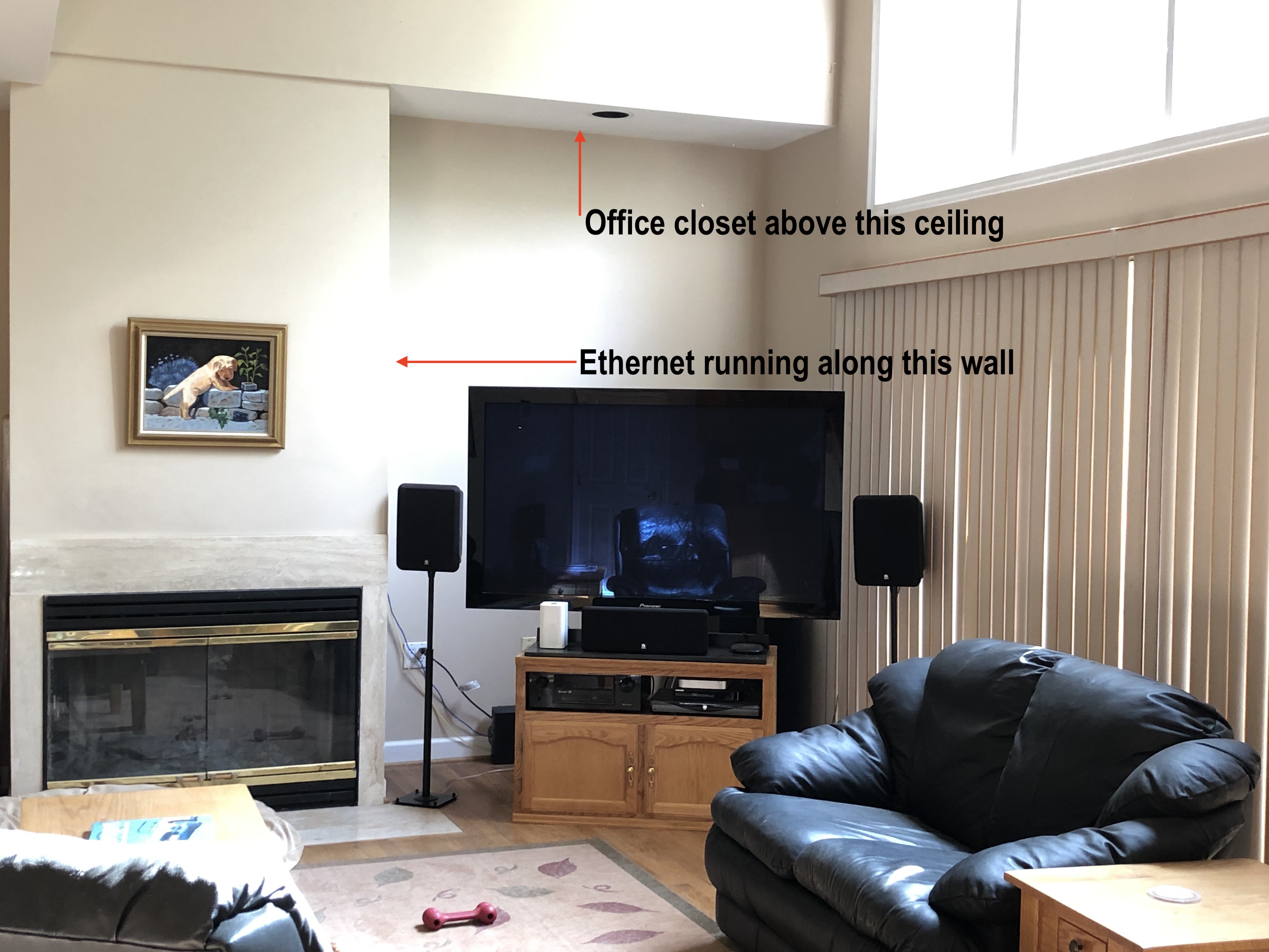
Focus your attention to the speaker on the left of the TV. Behind it, you’ll see a yellow and another blue Cat5 cable. Those were actually running along the side of the drywall column that hides the fireplace and chimney, as noted in the pic. Right above the TV: the closet for my second story office. So the cables were running down along the wall, but I screwed up and ran pre-terminated cables. I’m not so good at terminating Cat5; L1 isn’t my bag. The cables were too short, and you can see them arcing towards the Ethernet jack behind the TV.
Just sloppy. But it worked. So I left it that way for several years.
All interconnects were GigE, including to the servers, Windows PC, etc. And that was fine for the longest time. Then I went and bough that 2019 Mac Pro with its two 10GigE interfaces. Hm.
Time To Upgrade!
Obviously, to handle 10Gig, I’d need to replace the Cisco managed GigE switches I had. I decided that I was going to do two of the three: the living room switch could stay GigE for now and probably for .. ever. But the office and basement switches would get bumped.
The Basement: Cisco SX550X-16FT 16-Port 10G Switch
I don’t have any photos of the basement setup as it’s a disaster zone. But, the switch of choice for the basement is the Cisco SX550X-16FT. This is a switch that has eight 10GBASE-T ports, and eight more 10Gig SFP+ ports. While I was at it, I grabbed a set of 2x10GigE PCI-E cards for the servers and router in my basement. The card in question: the Intel X520-DA2. And finally, six short 10GigE DACs so that I wouldn’t need to add optics to the switch after the fact. I could just connect the DACs to the switch and servers, using the empty SFP+ ports.
Router
I have three VLANs in my house: two wired and one for the wireless network. The router has to live on all three of those VLANs, as well as the public-facing interface towards the Verizon FIOS ONT. Since I only bought a single 2-port card for the router, I had to share one of them. I configured the switch so that one of the 10GigE ports facing the router was a simple access port for that VLAN. The other one was a trunk port, carrying the other two VLANs including the wireless one.
With that, I had to configure VLAN trunking on FreeBSD, which is silly easy to do. I also had to re-do my /etc/pf/pf.conf to work with the new interfaces. But fortunately that was simple because of all of the variables I have at the top of said config file. Before too long, the router was back up and running the entire network.
Main Server
My joker server spans both wired VLANs in the house. But I decided I wanted to allow the server to use both of its 10GigE interfaces in a bundle, with VLANs. That way if one of the VLANs needed more than 10GigE and the other didn’t, it would work out. One 802.3ad bundle coming up; that was configured on the switch and set to trunk the two wired VLANs. Joker was also configured to put both of its new 10GigE interfaces into a bundle, and to do VLAN trunking on it.
Done. Easy.
Fileserver
My fileserver, bane, only needs to exist on one of the wired VLANs. Like with the joker server, I wanted to use both 10GigE interfaces in a bundle. But this time, it was done as an access port for that VLAN. From the fileserver’s perspective: a simple 802.3ad bundle with an IP address on it. Done. The fileserver was up and running in no time.
Other Connections
The basement switch is the hub that the other switches spoke off of. So I had to create two more 2-port 802.3ad bundles, but I had to use the 10GBASE-T ports for these since they were going to be connected to that run of Cat6 cabling from the living room. The switch in the living room reconnected in no time, and I was passing traffic between the media consumers in the living room and the switch in the basement.
The challenge was the office switch, which also got bumped to 10GigE. That connection wasn’t as clean given the crappy Cat5 cables running through the ceiling in the living room and down to the 4-port jack. I knew I wasn’t going to get 10Gig between the two of the switches with those connections. As it turns out, in the process of jostling cables around, one of the two cables between the office and living room went bad. The two switches couldn’t negotiate even a simple GigE connection over it. So I shut it down and left the remaining link between the two running at GigE speeds.
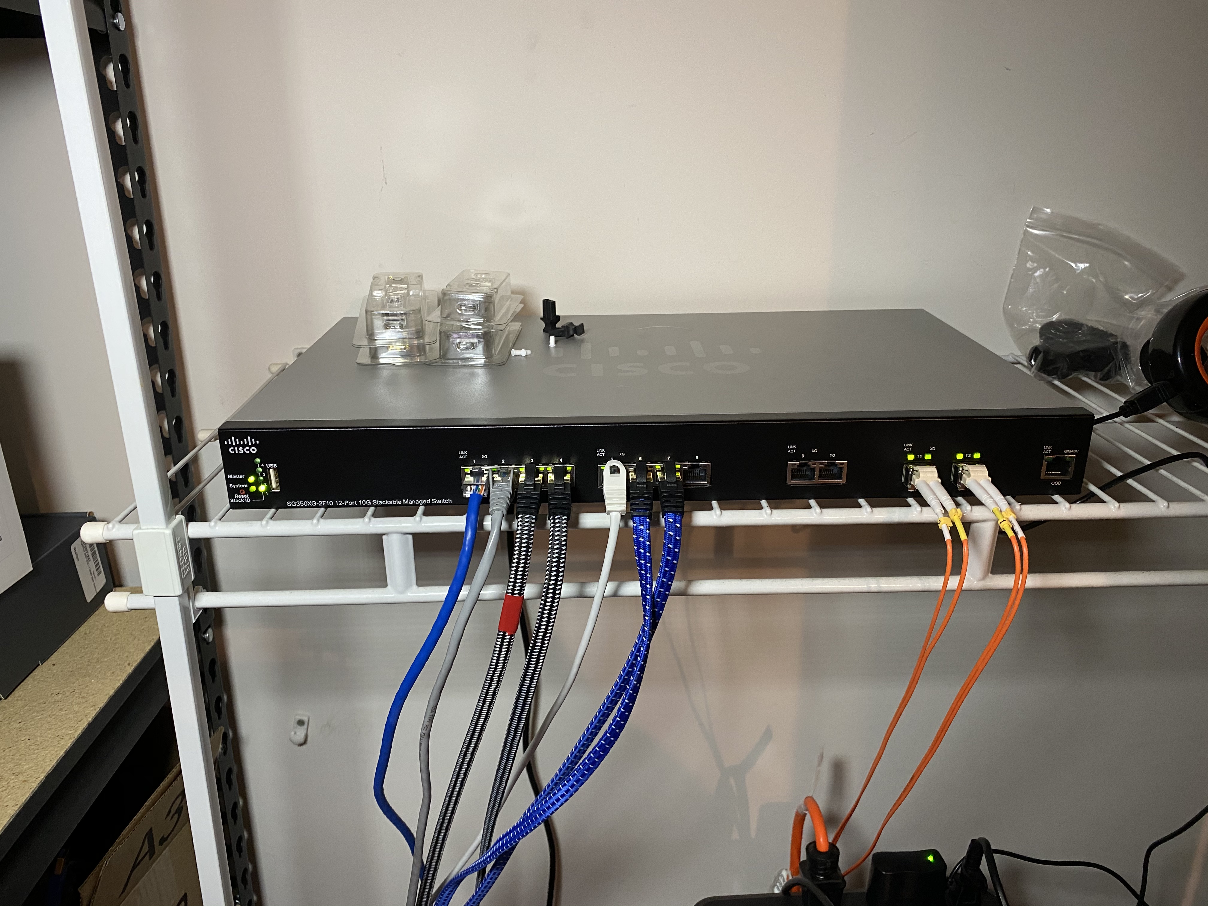
The Office: Cisco SG350XG-2F10
The switch I put in the office is slightly older than the one in the basement: the Cisco SG350XG-2F10. It has 12 10GigE ports on it, two of which are SFP+ ports. At the time of purchase, I didn’t think I’d be using the SFP+ ports for anything so I didn’t buy any optics for them. I knew that all of the connections in the office would be copper, and I had a plan for the link between the office and basement switches that would also involve some heavy duty shielded copper. I’ll get to that last point in a moment because it’s a whole story on its own.
Mac
The Mac has two 10GBASE-T ports on the back of it, and I ran them both to the new switch. Like joker, the Mac spans both wired VLANs in the house. So, simple access ports on the switch, and sure enough the Mac came right up.
PC
The PC’s motherboard has a single GigE port, along with another 10GigE port. It never really dawned on me that I’d use that integrated 10GigE port for anything, but that changed with this project! The primary interface for the PC continues to be its GigE interface. But the 10Gig is now available so that the PC mount one of the Mac’s exported filesystems over it. This is used when I’m recording game play on the PC: the software just dumps the captured game play right over the 10GigE interface to the Mac’s filesystem. And it happens in a flash.
Laptop
I figured while I was at it, I could add a 10GigE interface to my Mac laptop dock. Since I work from home 100% of the time and have a corporate MacBook Pro, I have CalDigit TS3+ Thunderbolt-3 docks connected to it for displays, keyboard, mouse, sound, and now networking. To one of those docks I connected a CalDigit TS3-to-10GigE interface adapter. And with that, the laptop now has 10GigE when it’s docked on the desk.
I Hate Layer 1! Or: Why Jason Shouldn’t Do Cabling
The interconnect between the two new 10Gig switches was going to be a challenge, mostly because I approached it incorrectly at first. The plan: run two 85ft lengths of Cat7 cable between the two, and terminate them both on either end with 2-port surface mount Ethernet boxes. I had to pick a new path for this cabling, because running down the same small hole in the office floor into the living room wasn’t going to work. Not with the new, fat Cat7. Let the adventure begin.
The Run
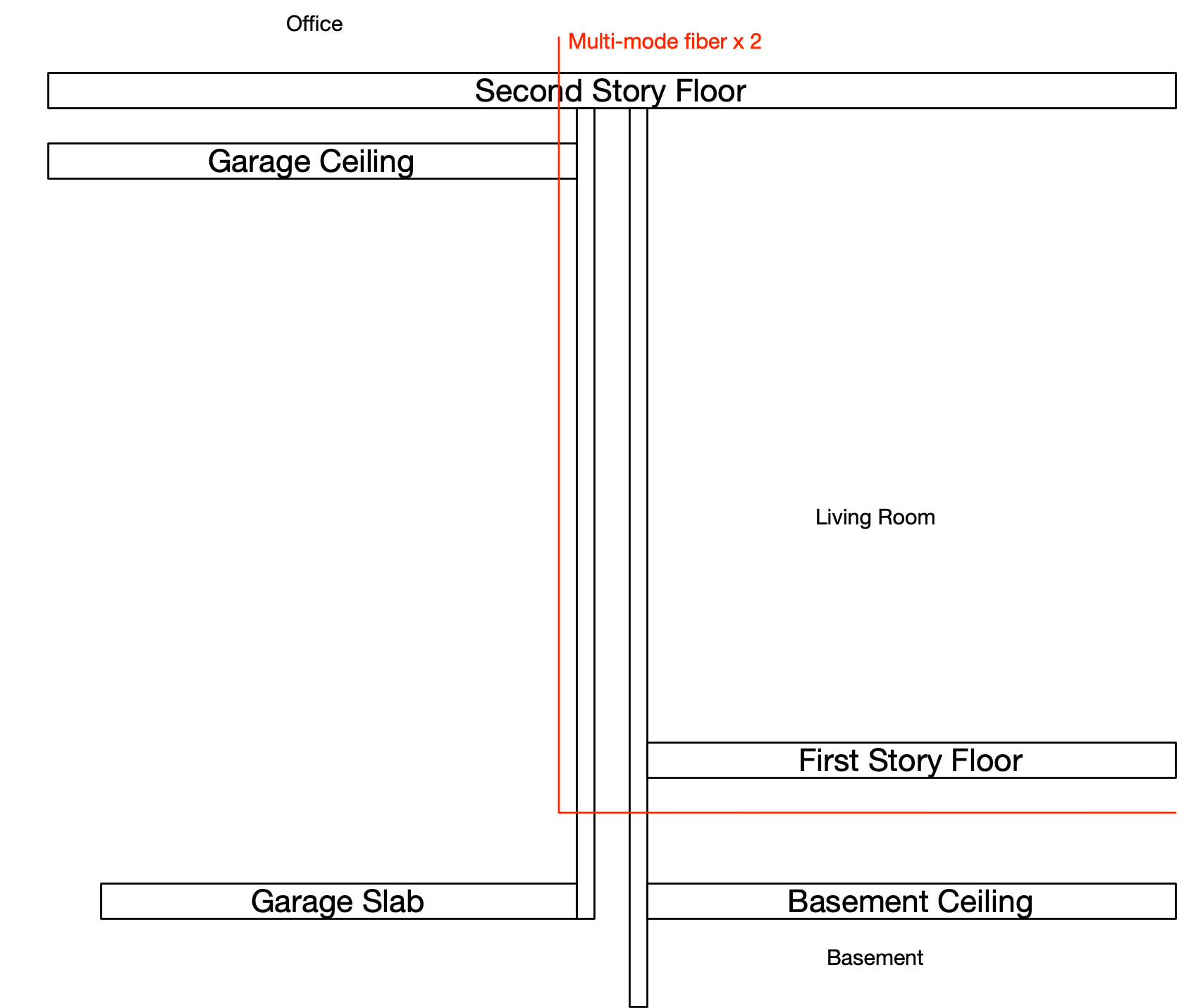
I mostly got fairly lucky with the physical run. I actually thought it was going to be the most difficult part of this process, and it turned out to be the easiest. My office sits above my garage, which shares a wall with the living room on the first floor. And, as it turns out: a wall with the basement. This because the garage’s slab is lower than the first floor. By digging into the drywall of the basement and garage, my buddy and I were able to see the path between the two was wide open and easy to use. It just took punching a small hole in the drywall in the garage, above the garage slab (of course), but below where the living room floor was. That put us right in the basement’s spacious ceiling.
And it turns out, the builders of the house left us a pull cable, too. My house was built in 1992 when cable TV was the rage. The basement had a chunk of coax running right next to the hole we made in the drywall, and it ended: right in the server room. It also ran across and above the ceiling, too. How convenient. Since I’m not now, nor ever will use that coax for anything, we cut it, tied the two chunks of Cat7 to it, and pulled it through to the server room. Easy!
As for the office, that was also easy. It took mutilating the drywall ceiling of the garage a bit, so that we could see the floor of the office above. I went into the office, and with a drill, punched a hole down into the garage. I fed a very long fish down that hole to my waiting buddy, who taped the two Cat7 cables to it. Up through the hole, and we were set.
Damn, that was easy!
The Fail
I was hoping that if I just followed the simple punch-down instructions for the surface mount boxes, I’d have two 10GigE connections between the two switches in no time. I had a set of pre-made Cat7 jumpers ready to make the connections on either end and was ready to go. I punched everything down and…
…nothing. I tried again. Nothing. What the? No matter what I did, I could not get link to come up. It just wasn’t happening. I did figure out what was going on much later, and I’ll get to that. So bear with me. But: this is why Jason should not do cabling. I’m just awful at it. And clueless about it, too.
The Fix
I decided it was time to stop playing around with copper and go fiber. I picked up two pieces of 85ft multi-mode fiber with LC ends on them, and a set of four LC SFP+ modules for the switches. While in the office, I clipped the two pieces of Cat7 and pushed them through the hole in the floor. They crumpled up on the garage floor below me. Fortunately the hole I drilled in the floor was just large enough for a single LC connector to slip through. So I carefully slide one cable, then the other down through that hole. And I connected the other end of the cables to the new SFP+ modules in the switch.
After retrieving the fiber from the garage ceiling, I cut the Cat7 again, right near the hole in the drywall that leads to the basement. Once done, I carefully(!) taped the new fiber to the Cat7 pull cable! In the basement, I first pulled the fiber in through the hole in the wall and let it collect into a small pile on the floor. Then in the server room, I grabbed that Cat7 cable and pulled. Voila: two MM cables in my hand, and into the switch. And voila again: 2x10GigE connections up/up and passing traffic.
Reason For Cat7 Failure
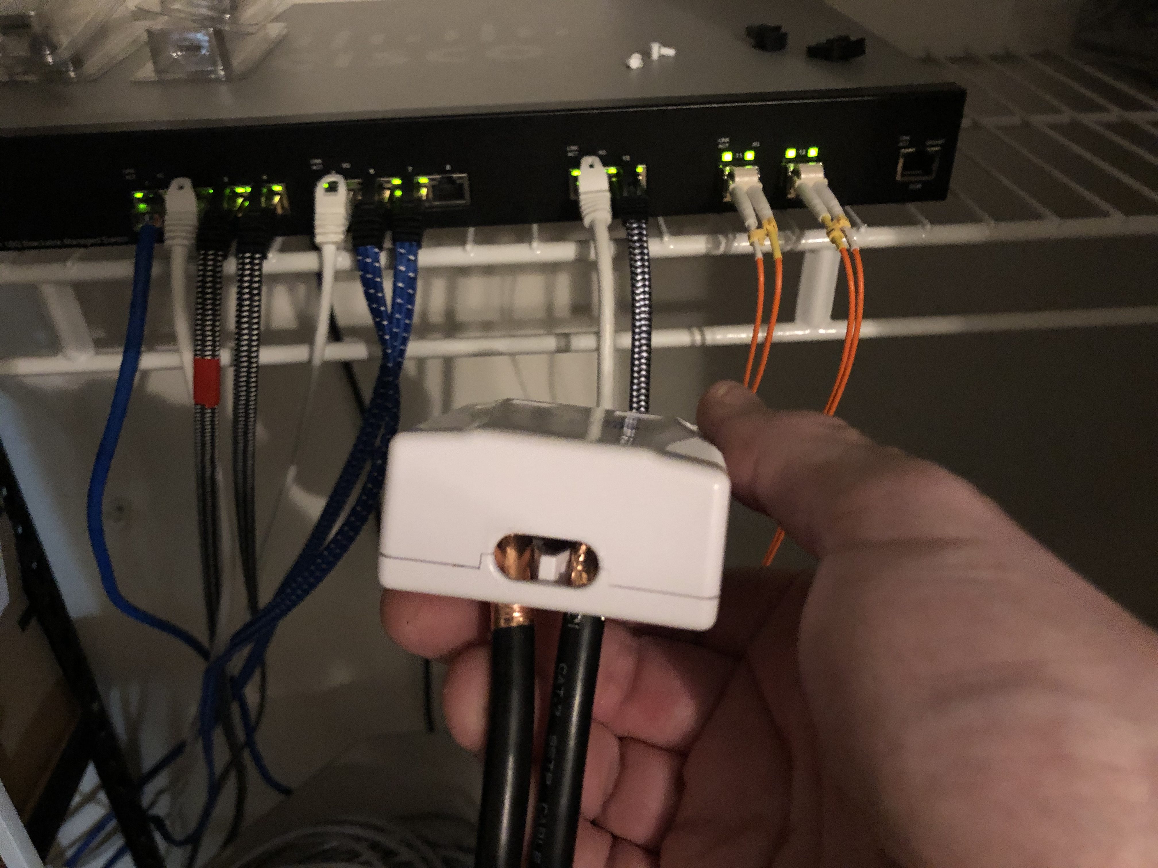
Shielding. That’s what it was, and what I simply didn’t understand. The surface mount boxes I was using had no way to “drain” the cables’ shielding. Cat7 is heavily shielded so it can carry 10GigE or more over very long distances. Far longer, as it turns out, than I needed. I could have just used unshielded Cat6. But oh well, I didn’t know. The fix, as it turns out, is pretty simple. There’s some copper tape that has conductive adhesive. If I put a small piece of that around the outside of the Cat7 cable, trapping a small braid of its internal shielding within that tape, it actually works with the surface mount box.
The photo below shows that. The Cat7 on the back side of the box is actually a single piece looped back on itself. Both ends with the copper tape, as you can see. On the other side of the box, I have two pieces of Cat7 running to the switch; the ports on the switch are configured with IP addresses so I didn’t create an Ethernet loop. Dumb I may be, stupid I am not! But, as you can see: both interfaces have link.
Conclusion: Future-Proofed

I don’t envision another bandwidth upgrade here at home in the near future. I spent over $3000 on those two switches, and that’s just silly. But it did make a marked improvement in capacity between the floors, and between various devices. No question. Since I decided to use multi-mode fiber, however, I’m future-proofed. There are optics today that provide 100GigE over MM fiber. They’re not SFP+ optics, but rather the QSFP form factor. And would require a completely different switch anyway. But the point is: in ten years when 100GigE is more affordable, I have the cabling infrastructure to support it.