Table Of Content
Redundant Layer 2: The Scourge of (Network) Scale

Preface
This write-up will consist of technical concepts, architecture ideas, and lots of opinion. All of which are based on 20 years of building big networks in datacenters. I’ve heard it all, seen it all, and have probably already built it. Some of the opinions in this article may come across as a bit cruel. They’ve been forged over those 2 decades of dealing with folks who don’t actually understand how to build scalable networks properly. Nor do those folks understand what kinds of trouble their requirements may put on the network.
Just bear all that in mind while reading.
General Architecture Concepts
This document will continually refer back to a fairly simple network architecture of: 2 routers and N top-of-rack switches. Each switch is assumed to be uplinked to both routers for redundancy. The vendor Arista calls this “leaf spine”, but it’s a network architecture that’s existed for a lot longer than Arista has existed. They just put a name to it (hint: it was probably invented at one of my former employers (while I was there)… ;-))
Redundant Layer 2: The Scourge of (Network) Scale
Let’s assume for the sake of this document that the word “scale” doesn’t mean, “adding a few more servers to my existing rack.” More like, “adding a bunch more racks full of servers to my existing datacenter.” With that, most competent server and system designers would say that the scourge of scale is the snowflake. A snowflake is a configuration that’s special, different than everything else around it. Snowflakes make it very difficult for server and systems admins to drive large numbers of servers. We’re talking 10s of thousands here, but even hundreds become very challenging with snowflakes. So let’s avoid snowflakes, for both servers and network gear.
The network has another problem child, and that’s the system designers’ insistence on having the same Layer 2 VLAN spanned to multiple switches. They either want the VLANs spanned because they want to have servers in different racks on the same L2 broadcast domain, or they want each server to have NICs attached to two different switches for L2 redundancy.
I call this the, “I wanna pony!” problem. When you say that, imagine the Simpson’s Ralphy character saying it with his squeaky voice.
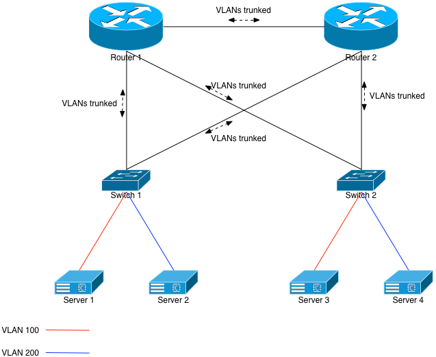
Figure 1 assumes the former: VLANs being spanned to different racks. The same concepts apply to redundant L2 networks where a server is connected to 2 different switches. The problem: Ethernet and its VLAN spanning technology. In order to provide full redundancy for each switch, both routers must have L2 knowledge of, in our example, VLANs 100 and 200. They would trunk both VLANs down to each switch, and across the link between themselves. The switches would, in turn, trunk both VLANs north towards the routers.
This build allows Server 1 and Server 3 to be on the same L2 broadcast domain. The same applies to Servers 2 and 4.
However, we’ve just built a classic Ethernet loop. Without any safe-guards in place, one simple ARP broadcast will turn into a storm, and the entire network will drop. The CPUs on the participating network gear will all go to 100% and they won’t even respond to serial console logins. The common safe-guard to put in place, of course, is the Spanning Tree Protocol (STP).
The way classic STP works is that, due to weights or preferences, various Ethernet links are put into BLOCK mode. They won’t allow Ethernet frames to traverse them unless something happens in the infrastructure such as a change in preferences, or a cable disconnecting, etc. Given Figure 1, the likely configuration would be to set Router 2 as less preferable, meaning the uplinks from Switch 1 and Switch 2 to Router 2 would be unused in normal, day to day operation.
STP works until it doesn’t. Friends at Juniper amusingly called STP a bug. Let’s imagine one of the routers in Figure 1 losing its brains and crashing. It crashes so badly that it loses any understanding of STP. At that point, it basically becomes a hub, and broadcasts out every packet it sees to every port. The entire STP infrastructure of that small network is now destroyed, and the CPUs of all network devices will go to 100%.
Spanning VLANs is Bad. Don’t Do It!
The network in Figure 1 is pretty small. It only has 2 routers and 2 switches. Imagine, however, 2 routers and 40 switches. Or 80. Or 120. Now imagine spanning VLANs 100 and 200 to all 120 of those switches. Debugging L2 issues over that number of devices is incredibly time consuming because things like ping and traceroute don’t exist for L2. And generally, when L2 problems arise, they take network devices down due to the aforementioned CPU issue.
Repeat after me: The top of rack switch is a single point of failure, and that’s OK! Again: The top of rack switch is a single point of failure, and that’s OK! If you’re scaling by racks versus by servers, you should assume that each rack is a self-contained failure domain. And if the switch in that rack fails taking out the entire rack, it’s OK because you have N other racks of servers, all providing the same services.
This is an important mindset to get into. It’s not a new mindset. We had this mindset at AOL in the 1990s. We were building servers and networks at scales no one short of Intel or perhaps the federal government were at that time. We understood the importance of independent systems operating with some autonomy, and not reliant on a single network fabric to tie them together. Fabrics fail, and when they do, the entire system goes with it.
Don’t do it.
No Pony for You!
The “I wanna pony!” folks all come out of the woodwork here: “But, but, but, I have to have my servers on the same VLAN!” Or, “I have to have L2 NIC redundancy for my servers!”
Why? Why do you need to have servers in Rack 1 on the same broadcast domain as servers in Rack 10? Why do they need to be on the same network? Do they have IP addresses and default routes on them? Of course they do. That means they can talk to one another.
And why do your servers need L2 redundancy? Is it because you’ve designed such a bad system that you can’t lose a server? Or a rack of them? Is your system actually that fault-intolerant? If the answer is yes to those questions, then you need to go back to the drawing board and learn how to design scalable systems better. I’m not going span VLANs so you can keep using the network as a crutch.
VXLAN: The Pony Lives
Now that I’ve hopefully talked you out of designing poorly-scaled systems, I’ll explain how network engineers can actually give you your pony with a little overhead and retain a rock solid network infrastructure. First we’ll look at another diagram that looks a lot like the first:
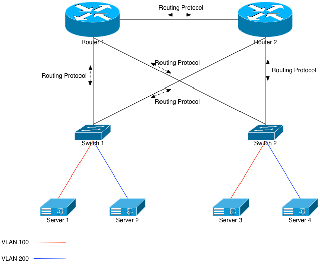
Let’s first assume that each switch is running a routing protocol with both upstream routers, and announcing its VLAN knowledge upwards via that protocol. That means Switch 1 and Switch 2 each have VLANs 100 and 200 configured on them, they each have Interfaces on both of those VLANs, and are both announcing those same VLANs up to Router 1 and 2. When Router 1 looks in its forward table for an IP address on VLAN 100, it’ll see entries for both Switch 1 and 2.
BGP vs OSPF
Which routing protocol to run between the network devices? I’ll discuss the differences, briefly, but it’s ultimately an exercise left to the reader. I’ll provide my opinions at the end of this section, but it’s your choice.
OSPF has very little (almost no) set up overhead. The devices just have to agree on an authentication (including no authentication) and the adjacencies will come right up. In contrast, BGP has a very heavy setup overhead. Each neighbor has to be configured. This can be simplified slightly with peer groups, but it’s still a 1-for-1 set up.
OSPF has nearly immediate link failure detection. It’s a link state protocol, and if the link between Switch 1 and Router 1 breaks, OSPF will quickly recalc and stop using that link until it’s repaired. BGP has timers that have to expire before it’ll remove broken routes, which may cause black-holing of traffic during that time. To alleviate that issue, BFD can (and should!) be deployed on these BGP peers; if a link goes down, the forwarding table will be adjusted immediately.
OSPF is an IGP, and therefore should not be filtered. In some cases, it can’t be. Generally, anything known in OSPF is told to (and accepted by) all adjacencies. BGP is not an IGP, and has a thorough set of filters that can be used for route propagation or prevention. Route maps can be written to dictate what’s announced, and what’s heard.
My recommendation is to use an external BGP peering between the switches and the routers. Use some form of automation to set new peers up and tear old peers out. Use the same ASN for each of the switches, only send the default route (0.0.0.0/0) from the routers down to the switches, and accept everything from the switches except 0.0.0.0/0. I like BGP because of that last suggestion: if someone accidentally configures an OSPF 0.0.0.0/0 on one of the top of rack switches, all networks on those routers will send their default traffic to that one switch. Bad things will result.
But again: it’s up to you. The important thing is to create a solid and stable L3 infrastructure.
The VLANs Aren’t Working!
If we follow the above suggestions and we have VLAN 100 (eg: 10.100.0.0/24) and VLAN 200 (eg: 10.200.0.0/24) configured on both switches, then Router 1 will see 2 entries for 10.100.0.0 and 10.200.0.0. It’ll ECMP between Switch 1 and Switch 2, meaning that 50% of the flows from outside of the routers will get to the right switch. The other 50% will not. We’ve partitioned the VLANs.
Oops.
This is where an overlay technology like VXLAN comes into play. Feel free to read the description of it on the Wikipedia site, but basically it’s just an L2 overlay on top of an L3 infrastructure. It allows devices (end points) to encapsulate L2 traffic inside tunnels and send it to other end points.

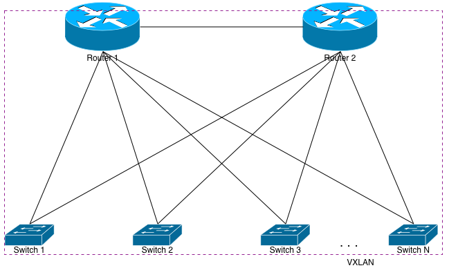
In our current example, we would tell Switch 1 and Switch 2 to become tunnel end points (VTEPS) and to connect to one another. This can be done using multicast, but doing so requires you to allow multicast through the rest of your network. I prefer to avoid that, so using unicast VTEPs is the more scalable solution. Each switch will have a locally configured way to encapsulate and decapsulate the VXLAN traffic, and send the resulting packets to the appropriate VLAN.
All of this happens via L3. The routers in this configuration still have absolutely no L2 knowledge of VLANs 100 or 200. They only know the L3 routes to those VLANs. Further, the switches aren’t physically connected together, and they’re using both uplinks to service this traffic. Server 1 will have ARP knowledge of Server 3. Server 2 will have ARP knowledge of Server 4. The best part is that this is all done without creating any L2 loops whatsoever. If something happens to Router 2 and it goes “stupid”, it won’t matter. Each device connected to it has an IP address on its respective port and isn’t a switchport. Therefore, no broadcast storms.
That Damned Hairpin!
Sticking with our current example, if a new flow comes into Router 2 destined for Server 3, there’s a 50% chance it’ll send the flow to Switch 2, which will send the frame right to Server 3. The other 50% of the flows will go to Switch 1. Switch 1 will be forced to encapsulate the resulting Ethernet frame inside VXLAN, and then send it to Switch 2 via Router 1 or 2. Our example of 2 switches means that 50% of the incoming flows will hairpin, assuming properly configured ECMP on the routers. More switches means a higher percentage chance in hairpinning incoming traffic. In fact, assuming n switches, the chance of hairpinning a new incoming flow is (100 – (100/n))%.
Each packet in that hairpinned flow will only hairpin once. Each participant (switch) in the VXLAN infrastructure is meshed with each other. That means that each switch knows exactly which switch the destination server is on. The traffic will never bounce from one switch to another, to another, to another, before finally getting to the correct switch. It’ll only hairpin off the routers once.

But let’s optimize that further. Doing so will assume the upstream routers can also participate in VXLAN. To make it happen, we’ll just mesh each switch with both routers as well as each other switch. We’ll also want to add VLANs 100 and 200 to both routers, along with L3 interfaces on those VLANs. Once that’s done, each router will immediately have MAC (ARP) knowledge of each of the downstream servers.
Assume a packet will come in to Router 1 destined for Server 1. Previously, Router 1 would see 2 entries in its forwarding table for 10.100.0.0/24 (Switch 1 and Switch 2), and it would ECMP the flows accordingly. But now that it’s meshed via VXLAN with the switches, its forwarding table lookup will return a directly connected interface: Interface VLAN100. Given that, it will learn Server 1’s MAC address (via VXLAN), and unicast the packet to Server 1 via Switch 1. It will do so after encapsulating the packet within a VXLAN tunnel.
This will happen each time, meaning no hairpinning of incoming traffic.
Benefits and Drawbacks
Benefits
VXLAN’s primary benefit is that it (finally?) gives the network engineer a way to provide the systems with spanned L2 VLANs, but in a way that scales better than raw Ethernet does. Specifically over a fault-tolerant L3 infrastructure. It can be done between 2 switches, 2 switches and 2 routers, or 200 switches and 2 routers. It doesn’t matter.
Further, all that’s needed is L3 connectivity between each tunnel end point. That means VXLAN can be used intra- as well as inter-datacenter. Now that brings with it other interesting challenges that systems would have to take into account, such as added latency. But it’ll work with some (actually: very little) care and feeding.
Drawbacks
While VXLAN is being baked into all of the latest merchant silicon, it’s still incumbent upon the network vendors to write code in their respective operating systems to take advantage of it. Most have, but some are still dragging their feet and refuse to adopt.
Further, VXLAN’s primary benefit is also a potential drawback: you have to manually configure each tunnel end point to mesh it with the rest of them. Vendors such as Arista provide a way to do that automatically using their services. Or the network team can write automation to handle the addition and subtraction of VXLAN TEPs. Neither of these are more or less advantageous, but it’s something that must be kept in mind if the idea of manually meshing a lot (eg: 120?) switches together with their upstream routers seems daunting.
Another small drawback is the encapsulation. It adds a small amount of overhead to the Ethernet frames. If you’re not running jumbos through your network (and… why aren’t you?) then you’ll get fragmentation for TCP connections, which will probably end up failing. Make sure any link in which a VXLAN tunnel may traverse has an MTU set higher than the end point servers’ MTUs.
Finally there’s a tiny bit of potential confusion while troubleshooting. But that’s easily overcome with exposure. You have to remember to check the VXLAN MAC address table as well as the normal MAC address table. You also have to remember that traceroutes into the network will have 1 less hop than out of the network. Each switch is still providing the local default route for the servers, so that’s the first hop their outgoing traceroute will hit. If the destination is outside of the network, then the next hop will be the router. Incoming traceroutes will first hit the router, and then be turned into an L2 packet which traceroute won’t see. But again, it’s just exposure.
Applications
So what can you do with this technology? How can you apply it to your network in the real world? Well, how about VMWare? Are you still one of the companies deploying VMWare’s ESXi at scale? Are you using VMWare’s God-awful VMotion technology to move VMs between your hypervisors because the systems running on it can’t deal with failures? Well, you’re in luck. You can span the VMotion and production VLANs between each of the switches as shown in the examples, and then VMotion your VMs to your heart’s content. In other word: use the crutch.
OpenStack is the hotness right now. Unfortunately, the networking part of OpenStack, Neutron, is still maturing. And it has a long way to go. If you’re using Tenant based networks with OpenStack, you’re also using Neutron as a gateway so that it can NAT connections for your tenant. And if you want your Neutron infrastructure to live in different racks for some rack redundancy (a good thing!), then the VLAN for the NAT (public) side of the Neutron boxes in each rack needs to be spanned. That way if your tenant gets attached to a Neutron box in Rack 1, it’ll have the same external NAT IP as it would being attached to a Neutron box in rack 3. Well, VXLAN can virtually span those public VLANs for you so that you don’t have to trunk them between the switches.
What about the back side of Neutron, and the Compute nodes? Well, they actually have VXLAN built in, because it’s part of Open vSwitch. So the servers can create virtual VLAN spans between them, even if they’re in different L3 domains in different racks.
There are lots of other applications of this tech. How about a load balancer connected to your routers somewhere in your network? If it has to send L2 traffic to the target servers because those servers need to see the real client IP address (ie: XFF headers won’t work), then you can VXLAN the load balancer to the switches that the target servers live on.
Summary
I’m not a fan of providing this crutch to system builders. It’s like being an enabler for a drug user. They’ll continue to lean on the crutch until it’s kicked out from under them, and the result will be: poorly scaled systems. Unfortunately, it’s a rare instance where a network savvy person actually has the final say in a system architecture. That means the network engineers and architects will be forced to designed compromised networks. VXLAN allows them to provide that crutch without the compromises.
2 thoughts on “VXLAN: Providing Ponies for Bad System Designers”